The wall clock project
Time flies so we always have to know it precisely. Plain old manually synchronized clocks are good but I’m tired of their inaccuracy and season based mandatory shift still not cleared EU wide. So I wanted to find a nice and handy wall clock without these drawbacks.
First, I went with DCF77 clocks but there is no strong enough signal inside the rooms here. I had a pet project to build an ESP controller based DCF77 transmitter just strong enough to cover my flat. Beyond the potential legal problems can be caused by a permanent 77.5 kHz radio transmitter, because of the lack of radio related knowledge this project was stopped after a while.
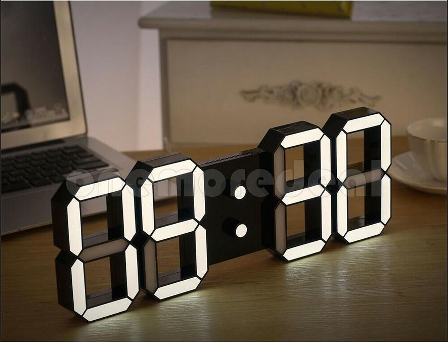
Finally, I found some nice internet based wall clocks on Ebay and Aliexpress so I bought a few. Later I noticed all of them were built on top of ESP microcontrollers. Great opportunities to customize. Right?
There was a small square shape clock fits perfectly for my desk. It has a simple but very practical software by default while Tasmota also supports it on some level. Unfortuantelly the other type of the clock I bough has less elaborate software: no proper time zone handling (DST is a nightmare) plus WiFi access point remains always active regardless it is needed or not: causing some security issue and extra radio noise.
My goal became to fix above mentioned bugs with the 2nd type of clock. Not a huge thing to live with but why to do so if we can consider those firmware problems like an interresting journey to do something nice. So I started to discover what I have and how to make it better. I describe how I did it.
Hardware
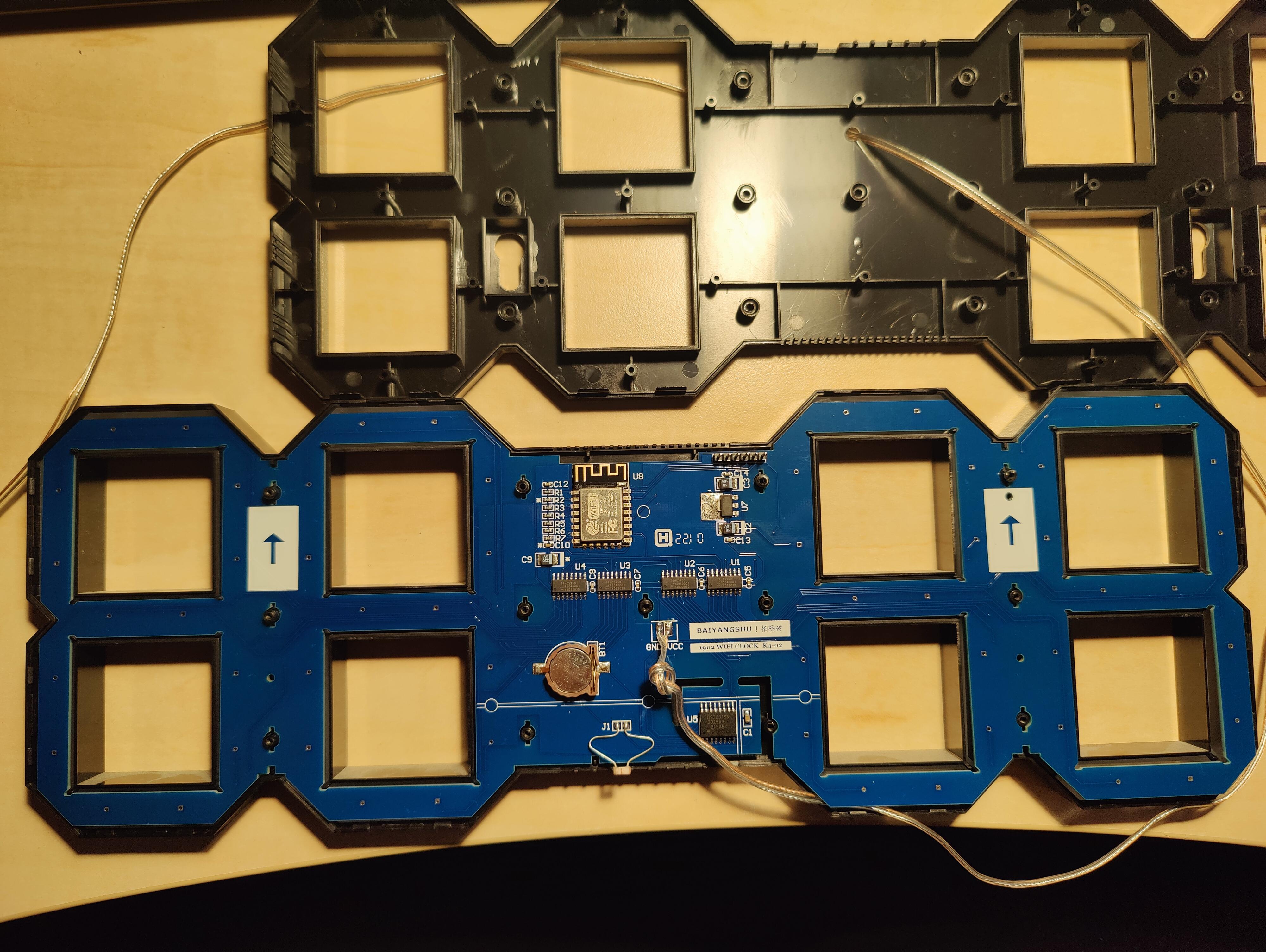
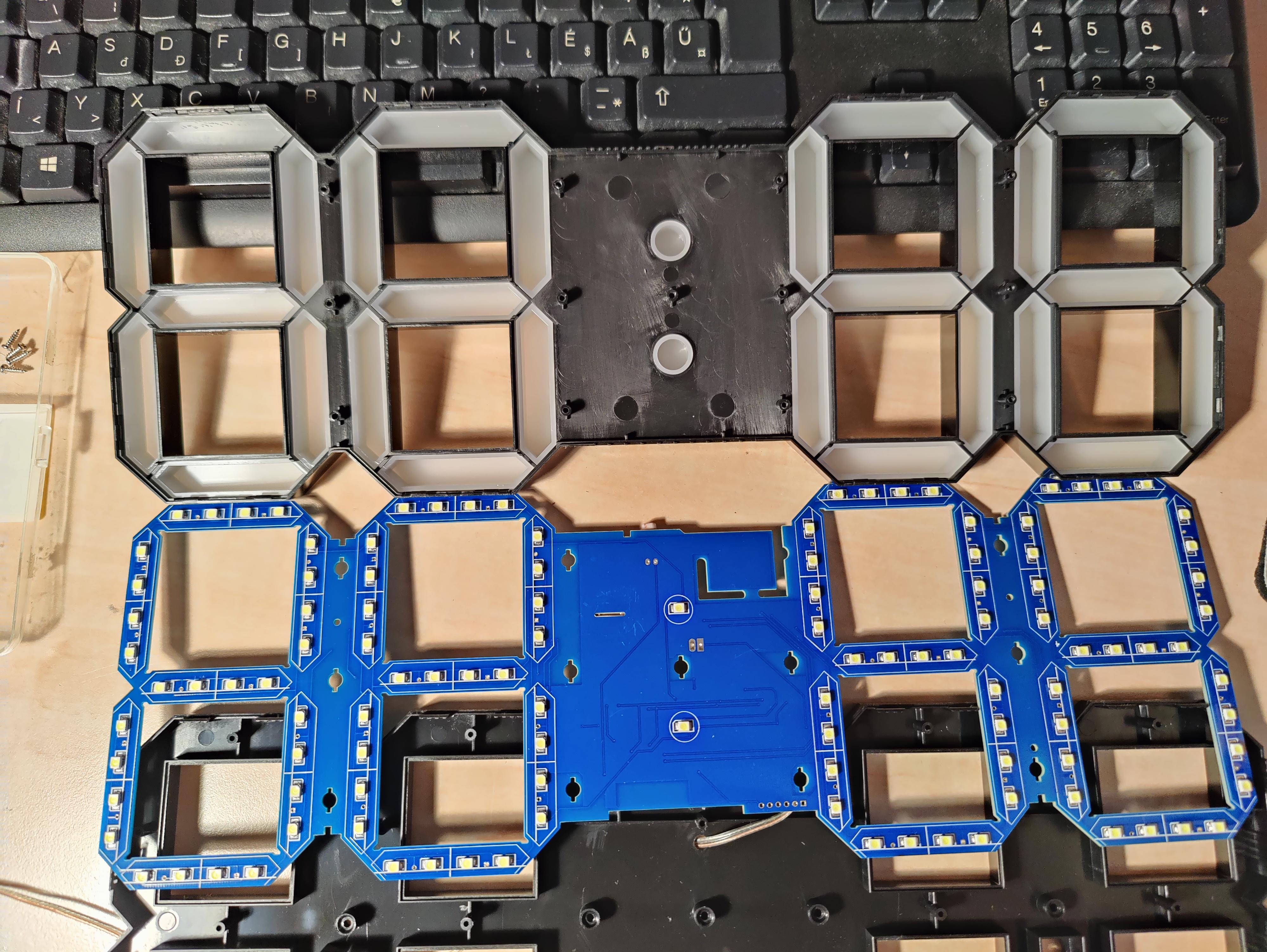
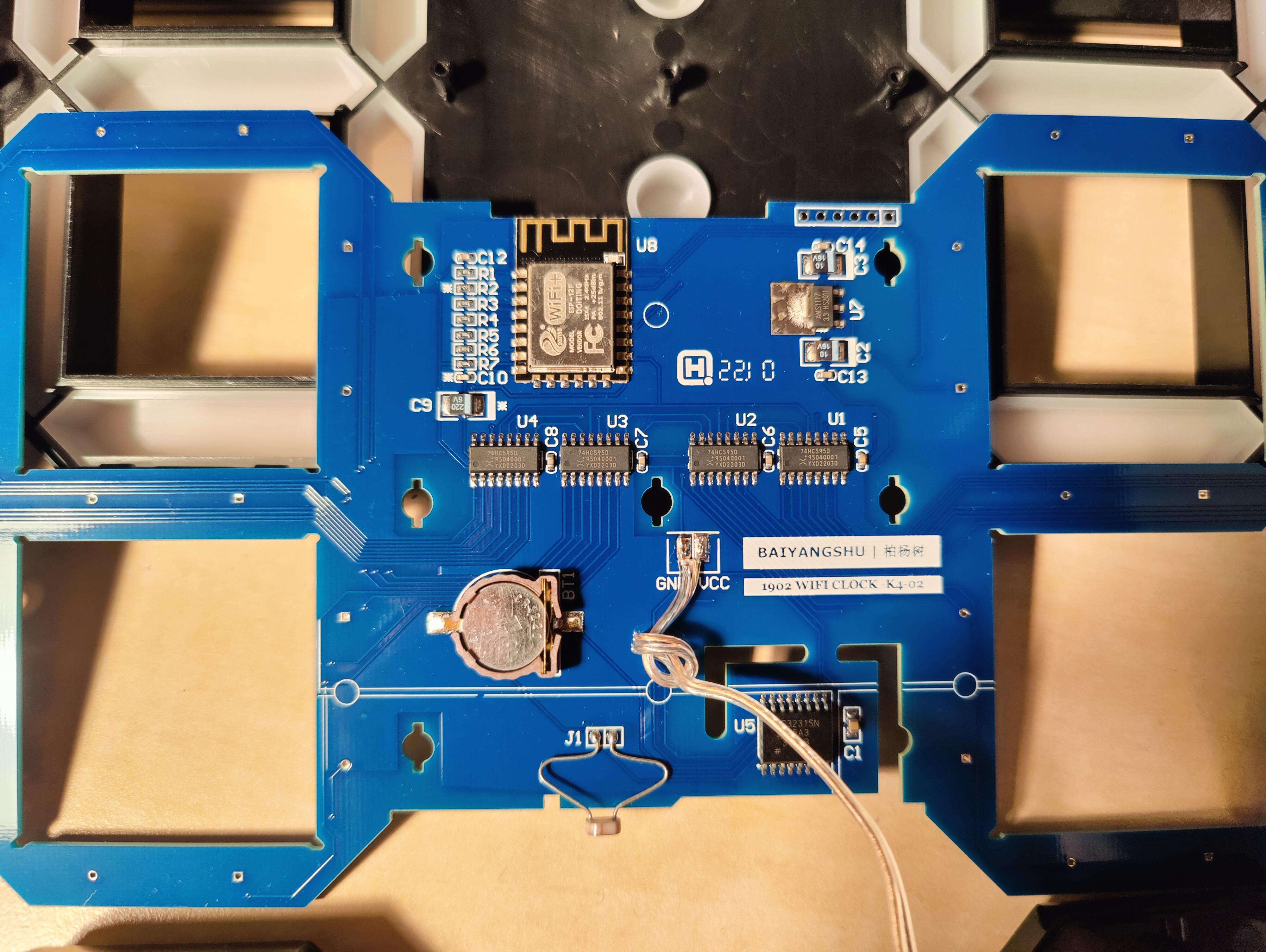
First of all, I had to discover the hardware I bought. After I removed the screws from the backside, I could snap it apart gently. It seems to be the best if you press the middle part of the box strong but not too strong.
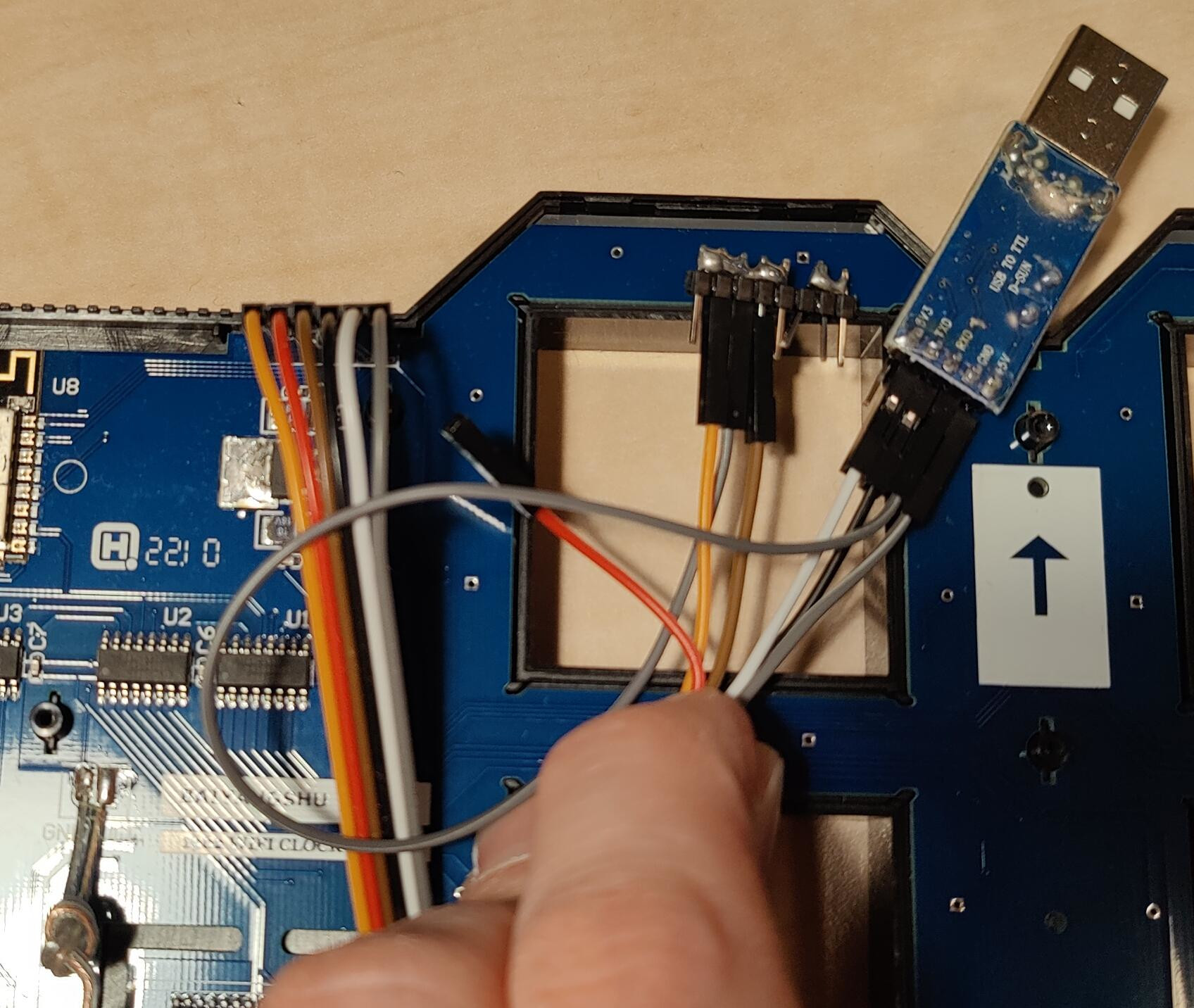
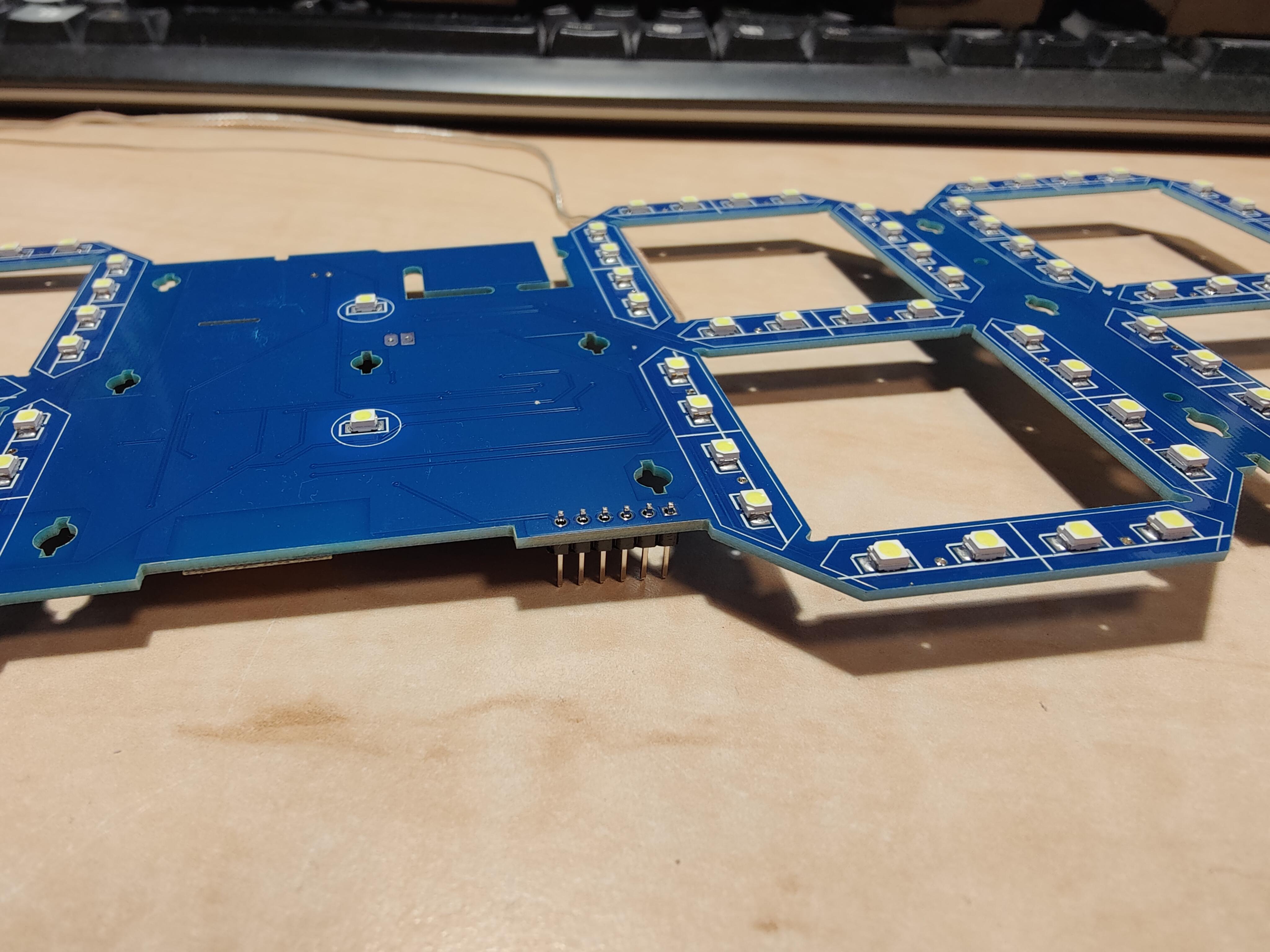
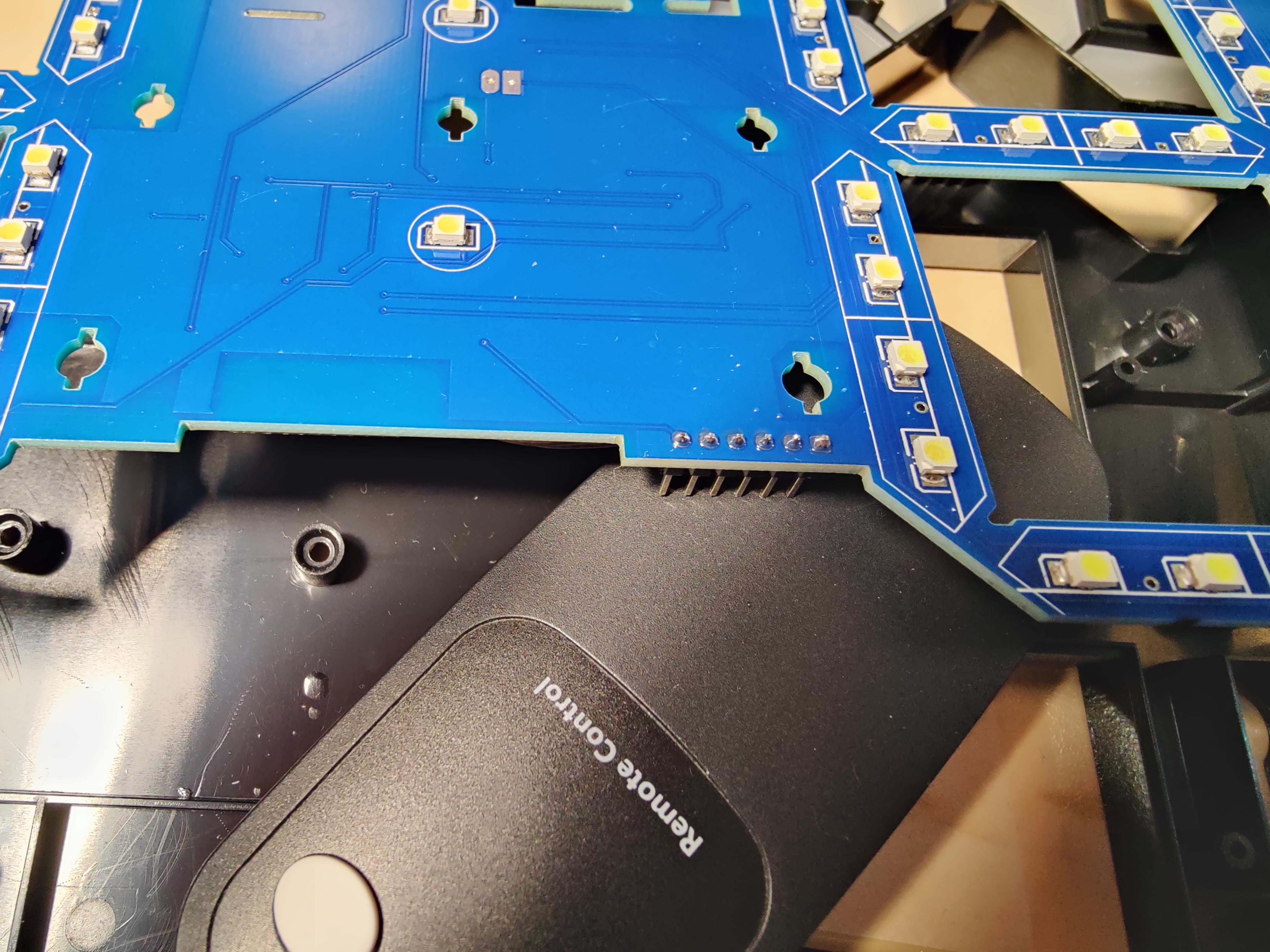
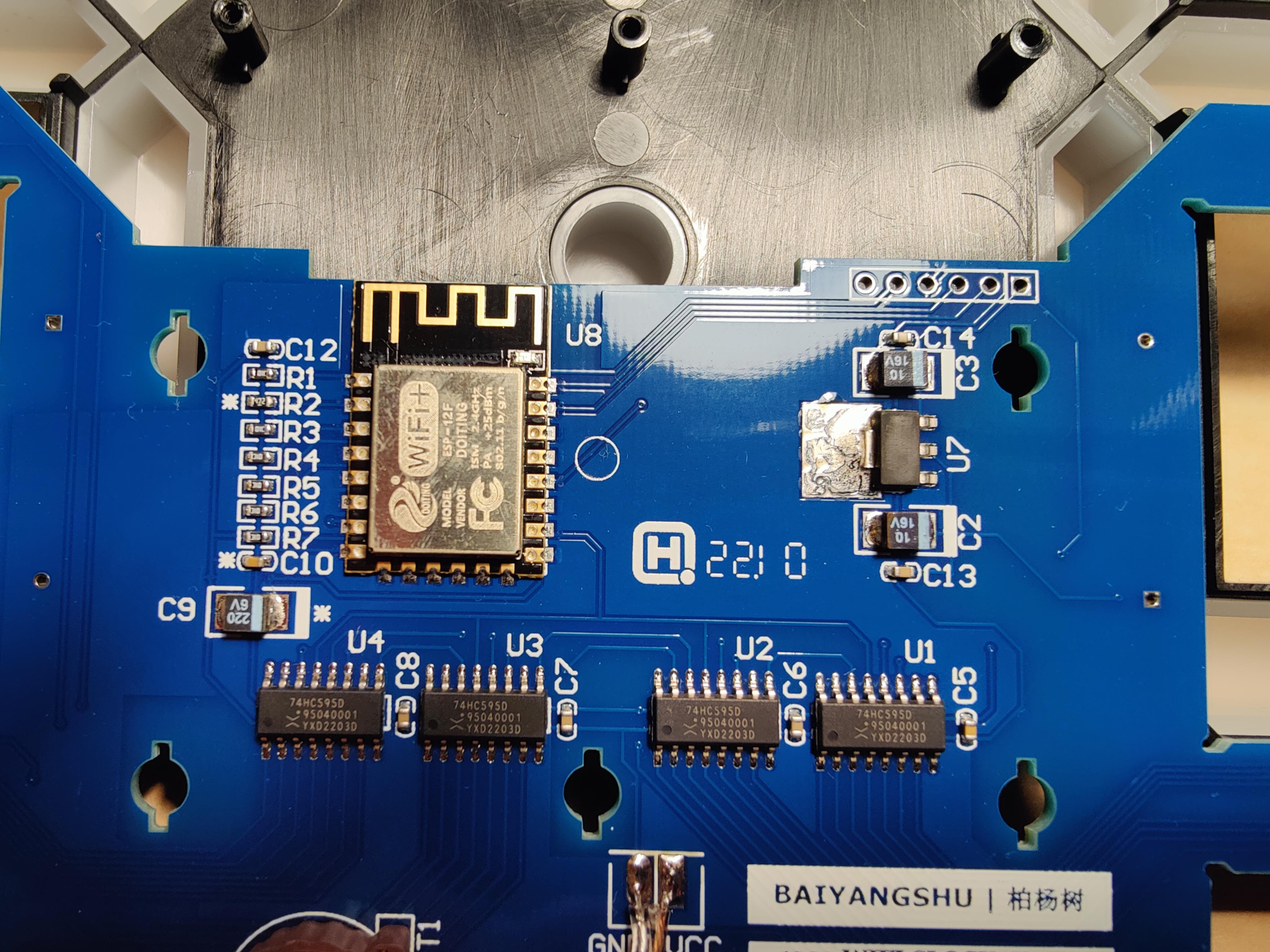
At the first glance, the most interresting part were the ESP12-F microcontroller and the unplaced 6-pin connector terminal. You can see that terminal on the top right corner, right to the ESP chip.
I found out which pin connected to where and there was no surprise at all: that is the programming interface connected directly to the ESP pins as drawn on the below picture. Luckily I had 2.54mm pin headers at home so I soldered it immediately.
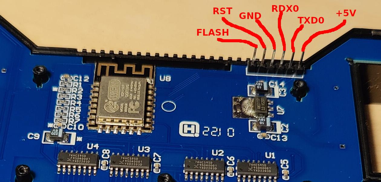
There is an AMS1117-3.3 voltage regulator chip to create +3.3V from the +5V of the USB connector soldered to the middle of the PCB. Nowadays USB is quite a practical power connector, however, I was a bit disappointed that only the power pins were wired out. Anyway, I can live with the internal programming header only and can accept this design as a valid engineering decision.
Inline with the marketing materials, this clock got a DS3231SM battery backed Real-Time-Clock chip (U5) controlled via I2C interface.
On the bottom of the PCB there is a photo resistor (J1) connected to the analog-digital interface (ADC) pin of the microcontroller.
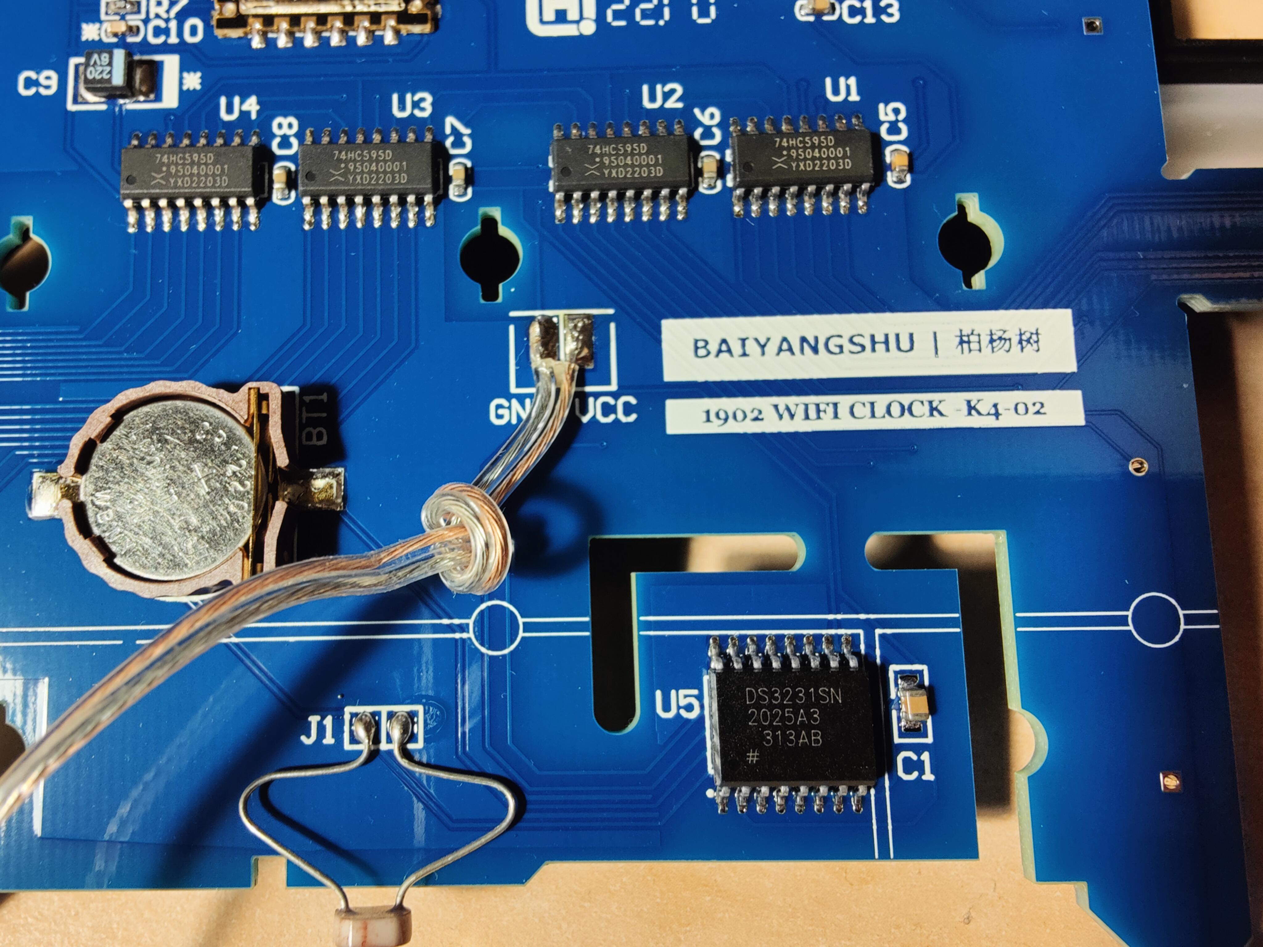
My beloved Amprobe multimeter helped me a lot to find out how the shift register array was built on the four 74HC595D shift registers (U1, U2, U3 and U4) and controlled by the ESP. Each pin of the shift register array control exactly one segment of the 7 segment 4 digit display. Two extra bits are dedicated for the second light build from two independent LEDs meaning that you can control them even separately. Each segment consist of 4 parallel wired LEDs. Very simple to write software for it.
It seems, all parts, except the shift registers, are built as the ESP reference design suggests. Personally, the most tough part of the reverse engineering was the light sensor wiring but after checking it with software that was quite obvious too.
Finally, I drawn the schematic for further processing, to write my own custom software. For this purpose, I used KiCad 8. It is a free and cross platform CAD software, works perfectly also on Linux.

Click on the schematic to open in full view.
Software
You can find my software here on GitHub.com. My intention is to publish not just the source code but a ready-to-burn kind of binary too.
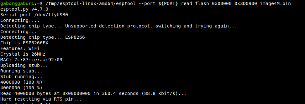
As part of the discovery, I have read out the factory firmware with esptool and a USB-TTL converter. Many people wrote about how to do so in details so I will not write about it now. I felt important to store that firmware for later and to make the opportunity to restore it, just in case.
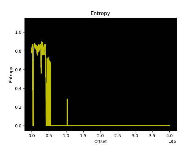
Just for fun, I studied the original firmware with binwalk and strings tool. With binwalk, I generated the below entropy drawing.
First, I wanted to write the new program in Micropython but when I noticed that my intended program might be too complex to implement in Python on that hardware with limited RAM I switched quickly to C++.
With C++ the biggest challenge was to look for a proper library managing some basic things such as WiFi and web user interface. I did not want to reinvent the wheel… So far WifiManager looks a good enough choice, however, it has some drawbacks too: for example, after first WiFi connection, web user interface remains off until I reboot the controller. Maybe I will fix it later.
I decided to use AceTimeClock library to have a precise clock. It deals with the RTC chip, NTP synchronization as well as manage different time zones with automatic switch over between winter and summer time. All time zones can be given by their name such as Europe/Budapest defined in tzdata. One negative thing I found is that AceTimeClock synchronizes ESP’s clock only once at boot with RTC chip in case of network outage then never again. NTP synchronization happens periodically which sets RTC chip too.
After I noticed strange numbers on the display I added Syslog capabilities to collect logs from my clocks on central log server. This might be useful for debugging furposes. For this purpose SimpleSyslog library is in use.
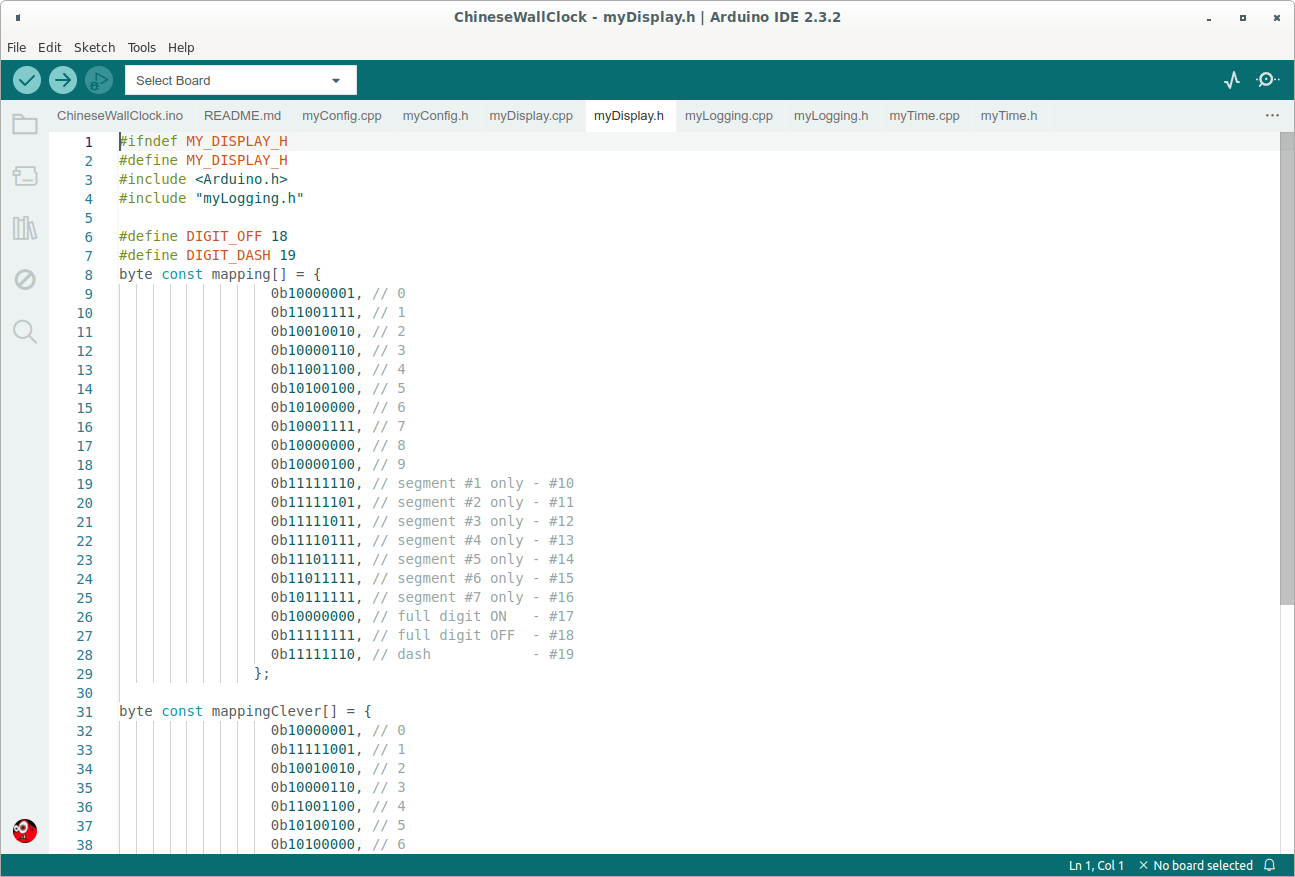
Based on the schematic I made, I known which pins of the ESP can control the display and how, but it was quite difficult to measure exactly which bit of the shift registers control which segment and which digit of the display. To find this out, I wrote a loop iterate over the bits one by one. This showed which bit turns on which segment. This way I could create the mapping have to send out to make a given number or sign visible. Logical zero means LED lights up, one means not.
Brightness control is done via the Output Enable pin of the shift registers: Arduino supports PWM easily. Only thing to keep in mind is that OE is an inverted pin of the shift registers. In case of automatic brightness control ADC pin of the ESP can be used to read value of light sensor. Logical connection between the sensor and the brightness control is very simple: ADC works on 0-1024 range while PWM on 0-512 range: divide it by 2. Using 512 as PWM value is not ideal even in the darkest environment as it means display is fully off so extrame value limitation is also needed.
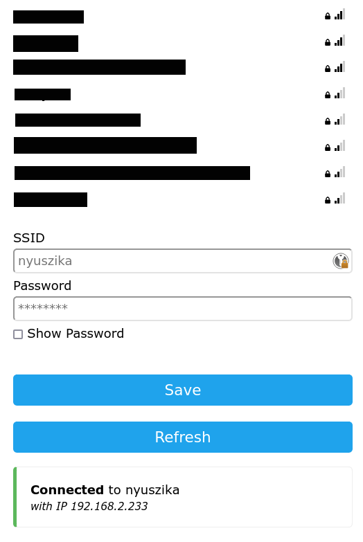
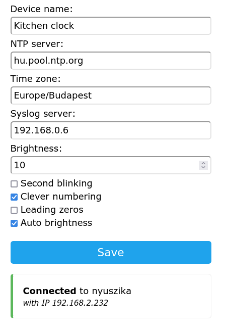
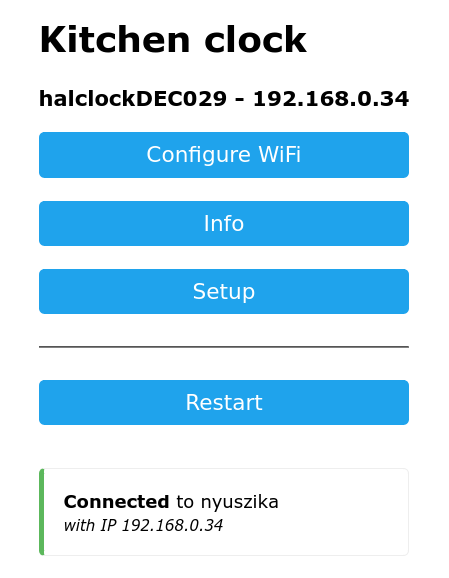
I drop some screenshots here about the web user interface of my software to illustrate its features:
Summary
I think this was quite a good hobby project. I learned about shift registers, ESPs, and noticed there are LEDs with embedded resistors. Just to mention a few. Last but not least now I have that kind of wall clock I wanted when I started to surf on the internet :)
Of course, there are still room to improve: adding IPv6 support or, for example, one can select time zone by typing the name of it instead of using a drop down choice. Drop down choice would be obviously much less error prone but so far I don’t know how to serve that huge list of choice where RAM is so limited.