How to read utility meters
Nowadays everything is smart. Everything is connected to the Internet. Everything can be controlled remotely. But what about utility meters? I wanted to know how to gather data from electricity-, water- and gas meters as frequently as possible.
First, I decided to study electricity meters as they seem the easiest.
At the time of writing this article, I live in Hungary. I will try to emphesize all the time when I am writing about country specific things.
Before anything could be done, we had to study not just the technical part of the topic but the legal part as well.
Technical part
There are two basic electricity meters in use in Hungary:
- One based on mechanical discs. This is quite an old style one and going to be replaced soon countrywide. These are the dumb utility meters, let’s say.
- Newer ones built with no mechanical parts but more and more digital components. Depending on the definition in the Hungarian regulation these can be smart or just remote readable. As per local legal definition, a smart meter is both remote controllable and remote readable.
It won’t be a surprise but I studied only the second type of the utility meters, even if plain old electricity meters could be read with help of camera and lots of power and computational overhead.
Digital electricity meters have at least an optical communication interface which makes it ideal for us. There is another widely used communication port on smart electricity meters: the so-called P1 port. P1 is even better for us from many point of view.
P1 communication interface
In Hungary, only the so-called smart meters have P1 ports used in households with higher electricity consumption or solar panels.
This interface was invented for consumer data sharing.
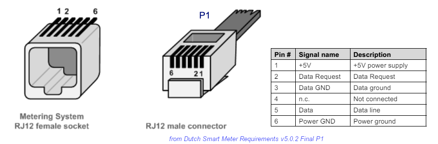
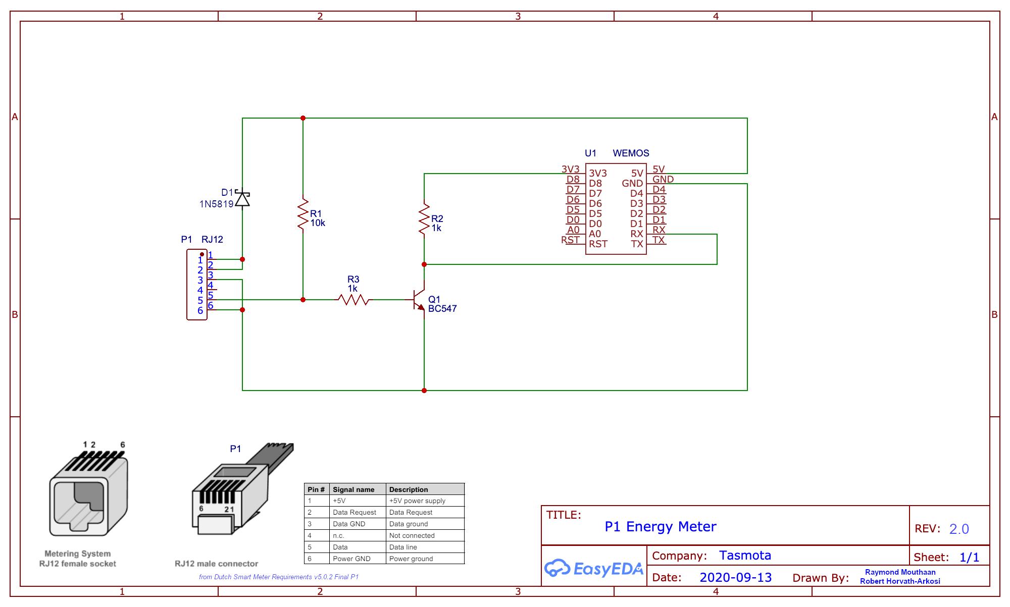
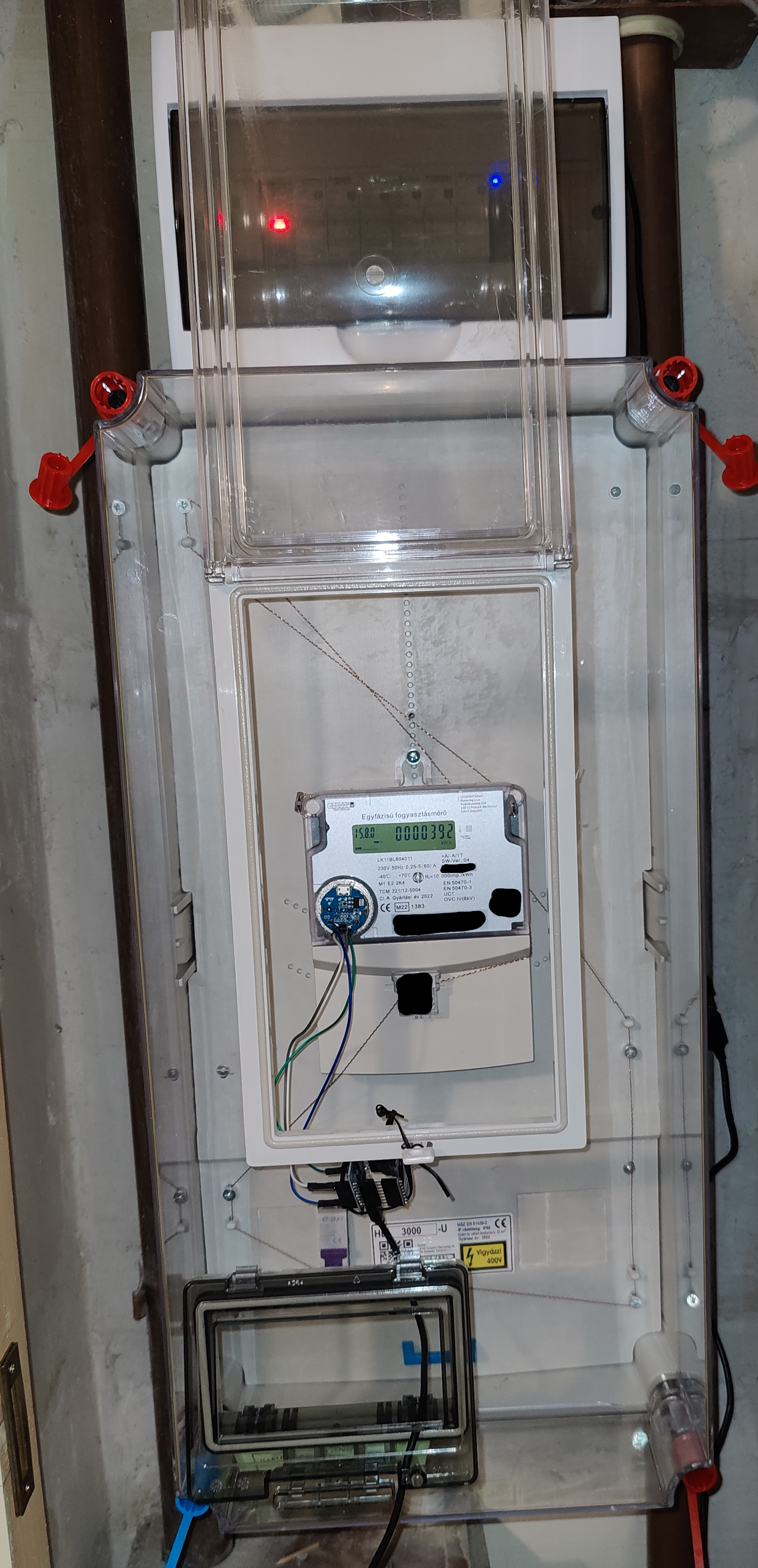
P1 port is a copper based solution with an RJ12 connector. It is usually covered by a rubber cap you can just simply pull out by hand.
As a safety measure, P1 is a one-direction only serial interface as it has only a TX data line physically connected to the RJ12 socket of the meter. RX line has been cut down from the socket.
As per version 5 of DSMR standard, P1 port provides up to 250 mA power on 5V for the device which is connected to it. Available power might be less depending on the version of the implemented DSMR standard but usually more than enough for a Wemos D1 Mini board for example.
DSMR 5.0.2 standard says the following about the electrical specifications:
- The P1 interface must provide stable +5V DC power supply via “+5V” (pin 1) and “Power GND” (pin 6) lines.
- All the lines of P1 port must be galvanically isolat-ed from the mains (Including +5V power supply line).
- The power supply must be able to continuously supply current IL_CONT <= 250 mA.
- The power supply line must be equipped with an overload / overcurrent mechanism, protecting P1 interface from excessive current by immediately shutting off the flow of current when it exceeds a level of IL_MAX >= 300 mA.
- Due to the use of optocouplers, the “Data” line must be designed as an OC (Open Collector) output, the “Data” line must be logically inverted.
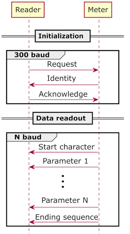
Communication protocol is based on NEN-EN-IEC 62056-21 Mode D.
Meters start to publish data if a “Data Request” line is connected to HIGH (+5V) and publish refreshed values every second (in my case 10 seconds) with 115 200 Baud, 1 stop bit, 8 data bits, no parity bit and 1 stop bit (8N1 format).
P1 meters send their data in text based datagramms.
A P1 datagram looks like /XXXZ Ident CR LF CR LF Data ! CRC CR LF
CRC is a CRC16 value calculated over the preceding characters in the data message.
Data contains COSEM objects identified with OBIS Reduced ID. Every object in the data section is separated with CR LF characters (carriage return / line feed).
Actual data meters provide depends on the number of phases (one or three phase meter) and maybe country regulations as well. Hungarian country regulations can be found in electricity distributor’s regulation (“Elosztói Szabályzat”) which seems to be inline with the related DSMR standard. Currently, we have actual voltage, current and total power (all per phase), frequency, exported and imported power and some weekly/monthly counters. For me, aggregated numbers are not relevant as I want to store measuremenet data in my own time series database for later processing and visualisation on my own. Anyway, I store everything: I can do data thinning anyway in case of need later.
Example P1 datagram (source: hup.hu)
/AUX59902722718 0-0:1.0.0(240304112520W) 0-0:42.0.0(AUX1030302722718) 0-0:96.1.0(9902722718) 0-0:96.14.0(0001) 0-0:96.50.68(ON) 0-0:17.0.0(90.000*kW) 1-0:1.8.0(022803.012*kWh) 1-0:1.8.1(015543.755*kWh) 1-0:1.8.2(007259.257*kWh) 1-0:1.8.3(000000.000*kWh) 1-0:1.8.4(000000.000*kWh) 1-0:2.8.0(000000.000*kWh) 1-0:2.8.1(000000.000*kWh) 1-0:2.8.2(000000.000*kWh) 1-0:2.8.3(000000.000*kWh) 1-0:2.8.4(000000.000*kWh) 1-0:3.8.0(001470.921*kvarh) 1-0:4.8.0(006381.114*kvarh) 1-0:5.8.0(001470.921*kvarh) 1-0:6.8.0(000000.000*kvarh) 1-0:7.8.0(000000.000*kvarh) 1-0:8.8.0(006381.114*kvarh) 1-0:15.8.0(022803.014*kWh) 1-0:32.7.0(233.9*V) 1-0:52.7.0(230.4*V) 1-0:72.7.0(232.7*V) 1-0:31.7.0(002*A) 1-0:51.7.0(002*A) 1-0:71.7.0(002*A) 1-0:13.7.0(0.968) 1-0:33.7.0(0.994) 1-0:53.7.0(0.927) 1-0:73.7.0(0.964) 1-0:14.7.0(50.03*Hz) 1-0:1.7.0(01.612*kW) 1-0:2.7.0(00.000*kW) 1-0:5.7.0(00.000*kvar) 1-0:6.7.0(00.000*kvar) 1-0:7.7.0(00.000*kvar) 1-0:8.7.0(00.417*kvar) 0-0:98.1.0(240301000000W)(022756.691*kWh)(015523.696*kWh)(007232.995*kWh)(000000.000*kWh)(000000.000*kWh)(000000.000*kWh)(001470.695*kvarh)(006356.208*kvarh)(001470.695*kvarh)(000000.000*kvarh)(000000.000*kvarh)(006356.208*kvarh)(022756.693*kWh)(02.304*kW)(02.304*kW)(01.104*kW)(00.000*kW)(00.000*kW)(00.000*kW) 0-0:96.13.0(..... ) !4454 /
Optical communication interface
Based on my experiences, the optical communication interface is the most widely used communication interface on power utility meters nowadays, however, the most poorly documented one too in Hungary.
Optical communication interface was invented for factory and service purposes not for the consumer so this might be the reason for the non-existent customer documentation. In some industrial installments, this optical communication port was used to collect weekly measurement points with a hand held unit on the spot.
The optical communication interface is active and physically reachable for most of the consumers. In some other cases it might be locked with a small (maybe sealed) cap or legal seal of the big standardized plastic measurement box. According to gossips, this port can be even disabled in a way such as unplaced semiconductors, but I doubt because in this case how the meter could be prepared before delivery. On another port under the cover we don’t know yet?!
In contrast with the P1 port, the optical interface is a bi-directional serial port where the consumer’s device drives the communication as master.
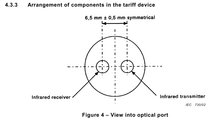
It works as an infrared light based serial interface.
Most of its parameters are defined by the IEC-620561-21 standard except the actual data package meters should provide. Values depend on the utility provider as well as the manufacturer of the meter.
To communicate with the meter we need to use a so-called optical head attached to the meter’s surface with a 27/16/5 mm sized Neodym N42 ringmagnet. First glance, it can be frightening the optical head uses a magnet but it is too weak to trigger the magnetic field protection of the meter.
IEC-620561-21 standard discusses data readout mode, programming mode and manufacturer specific mode. For us only the read-only data readout mode matters for data collection purposes. In theory, other modes are well protected and consumers should never have access to them.
This optical interface works as a master-slave bus where master is the hand held unit (or consumer’s device) and slave is the meter itself: client send /?! character sequence as a request then after a very quick handshake about the baud rate to be used in the rest of the communication meter starts to send current variable values such as meter’s serial number, software version and the total use of energy.
Legal part
I just write a quick summary about the Hungarian situation. Going into the details seems to be too complicated for an engineer as there is quite many iffy things around :)
If you want to use the optical communication interface, then well, it is tough. Tough because it seems to be unregulated in Hungary. So while you have quite a high chance you can use it, if you meet with an electric meter reader guy, you might get in trouble. Most probably they do not know anything about it. I asked the customer care about it: while they wrote quite a postive thing, it has became clear that they do know nothing in this topic.
If your meter has P1 communication interface (the copper one), you should use it. It is quite well regulated as well as documented so from legal point of view it must be safe to use.
Hungarian Energy and Public Utility Regulatory Authority (Magyar Energetikai és Közmű-szabályozási Hivatal; MEKH in short) stated that the power meter is the property of the electicity provider company. This means all the unregulated questions need to be discussed with the utility company.
MEKH also stated there is an “APN” based remote meter reader solution but it is a fully closed system; not in use among residental customers I suppose.
There is a high noise in the heads regarding the so-called smart meters, remote readable meters and “just” meters (“dumb meters” as I call them). They are all defined in the hungarian electricity distributor’s regulations (Elosztói Szabályzat) and the related Hungarian laws but not much people know these correctly I could reach via the official channels.
I contacted smart meter manufacturer companies and I got a few interresting hints but these are also a bit confusing. For example, one told me that gas meters are an absolutely no-go zone even if many of them have proper magnetic pulse transetter ready to use. Regulation of gas and water meters are still a black hole for me, to be honest, but sooner or later this will be also changed and prototyped.
So now you can see why I suggest you to use P1 port instead of optical one if it is also availabe (beyond the technical things such as power source).
Some details for Hungarian speakers
This section contains quotations from local legislations.
If you are not a Hungarian speaker please scroll down to here
The most important two legal documentations are
- 2007. évi LXXXVI. törvény a villamos energiáról (so called “vet”) and
- 273/2007. (X. 19.) Korm. rendelet a villamos energiáról szóló 2007. évi LXXXVI. törvény egyes rendelkezéseinek végrehajtásáról (so called “vhr”),
- National Authority for Data Protection and Freedom of Information, document number: NAIH/2018/3428/V - (original document location at the homepage of the authority)
however, there are some other provider specific documents too derived from this first two in Hungarian language only.
I try to add here those sections from everything which seems the most important from data collection point of view.
EON hálózat “P1 porttal, felhasználói interfésszel kapcsolatos általános információk” című dokumentum utolsó oldaláról (“2023.02.10”) (link):
“P1 porthoz való csatlakozás a fogyasztásmérő szekrényben
Alapvetően a felhasználónak nincs bejelentési kötelezettsége, a galvanikusan leválasztott portra szabadon csatlakoztathat felhasználói interfészt. Az esetek többségében ez meg is tud valósulni.
- Vannak azonban olyan régebbi fogyasztásmérő helyek, amik nem rendelkeznek kezelőajtóval és kettős plombálással vannak ellátva, ezek esetében zárópecsételt burkolat védi a fogyasztásmérőt. Ha ilyen mérőhelye van a felhasználónak, akkor jeleznie kell az igényét az Elosztói Engedélyes felé és Ő a bekötés idejére biztosítja a hozzáférést a mérőhöz.
- Az újabb szekrények és a régebbi fa szekrények is korlátozás nélkül biztosítják a mérő kezelhetőségét.
- Amennyiben a felhasználó igényli a SMART mérőt és a mérőhelye nem biztosítja a mérő kezelést, akkor érdemes a fogyasztásmérő szekrény előlapját cserélni vagy átalakítani (IP44 védettséget megtartva) olyanra, ami biztosítja a mérő kezelhetőségét. Vezetékes adattovábbítás esetén a kivezető nyílás nem okozhatja a fogyasztásmérő szekrény IP védettségének és tartó szilárdságának csökkenését. A kommunikációs kábel befűzése a felhasználó vagy regisztrált szerelőjének a feladata. A plomba bontást, fedél eltávolítást és visszazárást elvégezzük mi, ha szükséges, de a kommunikációs kábel behúzása és a mérőbe történő csatlakoztatása a felhasználó felelőssége.”
MVM ÉMÁSZ Áramhálózati Kft Üzletszabályzatából (“Budapest, 2022.10.03.”):
“2.62 Leolvasás: Jelenti a fogyasztásmérő-berendezés mérési adatainak a felhasználási helyen hálózati engedélyes által végzett leolvasását, az arra alkalmas fogyasztásmérő-berendezés mérési adatainak hálózati engedélyes általi távlehívását, valamint a fogyasztásmérő-berendezés mérési adatainak a felhasználó részére biztosított applikációval történő rögzítését;
2.80 Okosmérő: Olyan távlehívható fogyasztásmérő, amely képes a távoli utasításokat fogadni tájékoztatás, vezérlés figyelemmel kísérés és ellenőrzés céljából.
2.89 Távlehívható fogyasztásmérő: Olyan fogyasztásmérő-berendezés, amely képes a villamosenergia-fogyasztás és a villamosenergia-hálózatba táplált villamos energia mennyiségét mérni, a kiegyenlítő energia elszámolási mérési időintervallumának megfelelő gyakorisággal a mérési adatokat tárolni, valamint elektronikus távkommunikáció útján a mért adatokat továbbítani.
11.1.3 Előírások az okosmérő kialakítására vonatkozóan
[…]
Az MVM Émász Áramhálózati Kft. a felhasználó kérésére ingyenesen, korlátozástól mentesen és biztonságosan elérhetővé és megtekinthetővé teszi a felhasználó és a meghatalmazása alapján eljáró harmadik fél számára
a) az okosmérőből kinyert hitelesített fogyasztási adatokat, így a betáplált és a vételezett villamos energia mennyiségére és idejére vonatkozó adatokat,
b) energiahatékonysági programok, keresletoldali válaszintézkedés és további szolgáltatások igénybevételének elősegítése érdekében az okosmérőből kinyert nem hitelesített közel valós idejű fogyasztási adatokat.
A fenti adatok biztosítása megkülönböztetés-mentesen, átlátható módon, kommunikációs interfész alkalmazásával vagy távolról történő hozzáférés biztosításával történik. Az MVM Émász Áramhálózati Kft. az adatokat olvasható, az összehasonlítást és az értelmezést lehetővé tevő formátumban kell biztosítani. A szolgáltatott adatok tájékoztató jellegűek.”
“1. § (1) E rendelet alkalmazásában:
24. közel valós idő: a kiegyenlítő energia elszámolási időszakkal megegyező vagy annál kisebb időtartam;
31. Kiegyenlítő energia: az átviteli rendszerirányító által a pozitív, vagy negatív irányú menetrendi eltérést kiegyenlítő szabályozás során a mérlegkör-felelősökkel elszámolt villamos energia;
3. § E törvény alkalmazásában
11a. Elszámolási időszak: szerződésben megállapított, elszámolás alapjául szolgáló, két mérőleolvasás közötti időszak;
14/C. § (1) Az elosztó és a villamosenergia-kereskedő a honlapján, valamint – ha ügyfélszolgálatot működtet – ügyfélszolgálatán tájékoztatja a felhasználót az okosmérő és a hozzá kapcsolódó rendszer működéséről, különösen az okosmérő teljes körű funkcióiról, a felhasználó és az elosztó általi leolvasás menetéről, az energiafogyasztás figyelemmel kíséréséről, valamint a személyes adatok gyűjtéséről és kezeléséről.
(2) Az elosztó az elosztói szabályzatban és a villamosenergia-kereskedő a kereskedelmi szabályzatban külön fejezetben határozzák meg
a) az okosmérő által kezelt adatokat,
b) az adatkezelés célját és módját, valamint
c) azokat az előírásokat, amelyek biztosítják a felhasználó adatainak védelmét és az adatvédelemre vonatkozó jogszabályoknak való megfelelést.
(3) Az elosztó a felhasználó kérésére ingyenesen, korlátozástól mentesen és biztonságosan elérhetővé és megtekinthetővé teszi a felhasználó és a meghatalmazása alapján eljáró harmadik fél számára
a) az okosmérőből kinyert hitelesített fogyasztási adatokat, így a betáplált és a vételezett villamos energia mennyiségére és idejére vonatkozó adatokat,
b) energiahatékonysági programok, keresletoldali válaszintézkedés és további szolgáltatások igénybevételének elősegítése érdekében az okosmérőből kinyert nem hitelesített közel valós idejű fogyasztási adatokat.
(4) A (3) bekezdés szerinti adatok biztosítása megkülönböztetés-mentesen, átlátható módon, kommunikációs interfész alkalmazásával vagy távolról történő hozzáférés biztosításával történik. Az elosztónak az adatokat olvasható, az összehasonlítást és az értelmezést lehetővé tevő formátumban kell biztosítani. A szolgáltatott adatok tájékoztató jellegűek.”
NAIH/2018/3428/V számú Nemzeti Adatvédelmi és Információszabadság Hatósági ügyirat - 2018. május 23.
A NAIH/2018/3428/V számú NAIH ügyirat foglalkozik az okosmérőkkel gyűjtött adatokkal és deklarálja, hogy azokat mint személyes adatok szükséges kezelni.
Az adott ügyirat talán leginkább releváns részét beidézem:
“II.1. Az intelligens fogyasztásmérők révén gyűjtött adatok személyes adat minősége
Az Infotv. szerint személyes adat az érintettel kapcsolatba hozható adat, valamint az adatból levonható, az érintettre vonatkozó következtetés.
A 2018. május 25-től alkalmazandó Általános adatvédelmi rendelet (a továbbiakban: Rendelet) 4. cikk 1. pontja alapján személyes adat azonosított vagy azonosítható természetes személyre (érintett) vonatkozó bármely információ.
Az intelligens fogyasztásmérő által létrehozott adatok az esetek többségében olyan egyedi azonosítóhoz társulnak, mint a fogyasztásmérő azonosító száma. Ez az azonosító szám elválaszthatatlanul kapcsolódik a számláért felelős személyhez, más szóval a készülék, és annak azonosító száma lehetővé teszi az adott személy más fogyasztóktól történő megkülönböztetését.
Továbbá az intelligens mérési szolgáltatás keretében gyűjtött információk a fogyasztó energiaprofiljához kapcsolódnak, és ezeket az információkat az adott egyént közvetlenül érintő döntések meghozatalára használják. Ilyen döntés lehet az energiaszolgáltatásért felszámítandó bármilyen díj nagyságának meghatározása, ám az információk felhasználása nem csak számlázási célokra korlátozódik.
Ezek alapján tehát az intelligens fogyasztásmérő által rögzített adatok a felhasználók személyes adatainak minősülnek.”
How I communicate with the meters’ interfaces
There are ready-to-use devices on the market for this purpose (for example slimmelezer) but I feel them too expensive and, what is a much bigger problem for me, they are tied to a vendor cloud which is a privacy/security risk in general. On the other side, ready-to-use devices have nice boxes so you don’t need to worry about that part and you do not need to be an IT expert even to operate.
For me the easiest way to create a cheap device fully controlled by me is using an ESP microcontroller.
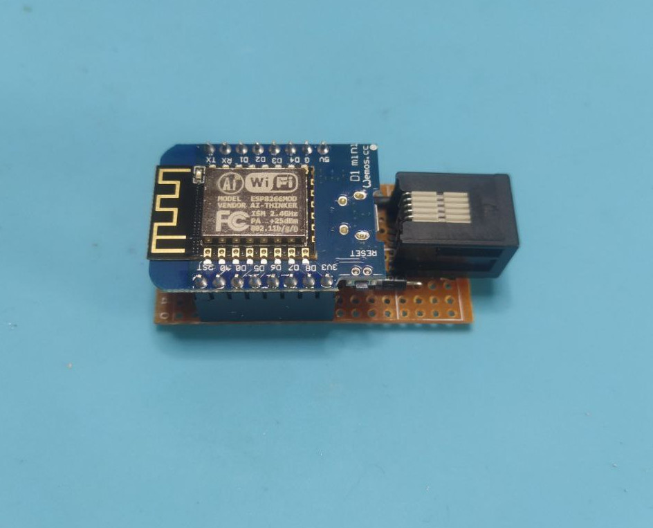
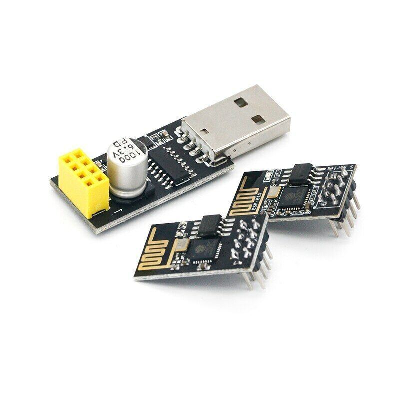
There are several tiny board with different ESP chips on them: smaller like ESP01S and bigger like Wemos D1 mini. My personal favorite for this kind of work is the Wemos D1 mini. Wemos D1 mini has two versions with not much diffences. The reason why I prefer to use version 2 of Wemos D1 mini is the USB-C typed socket on it which is way more common nowadays.
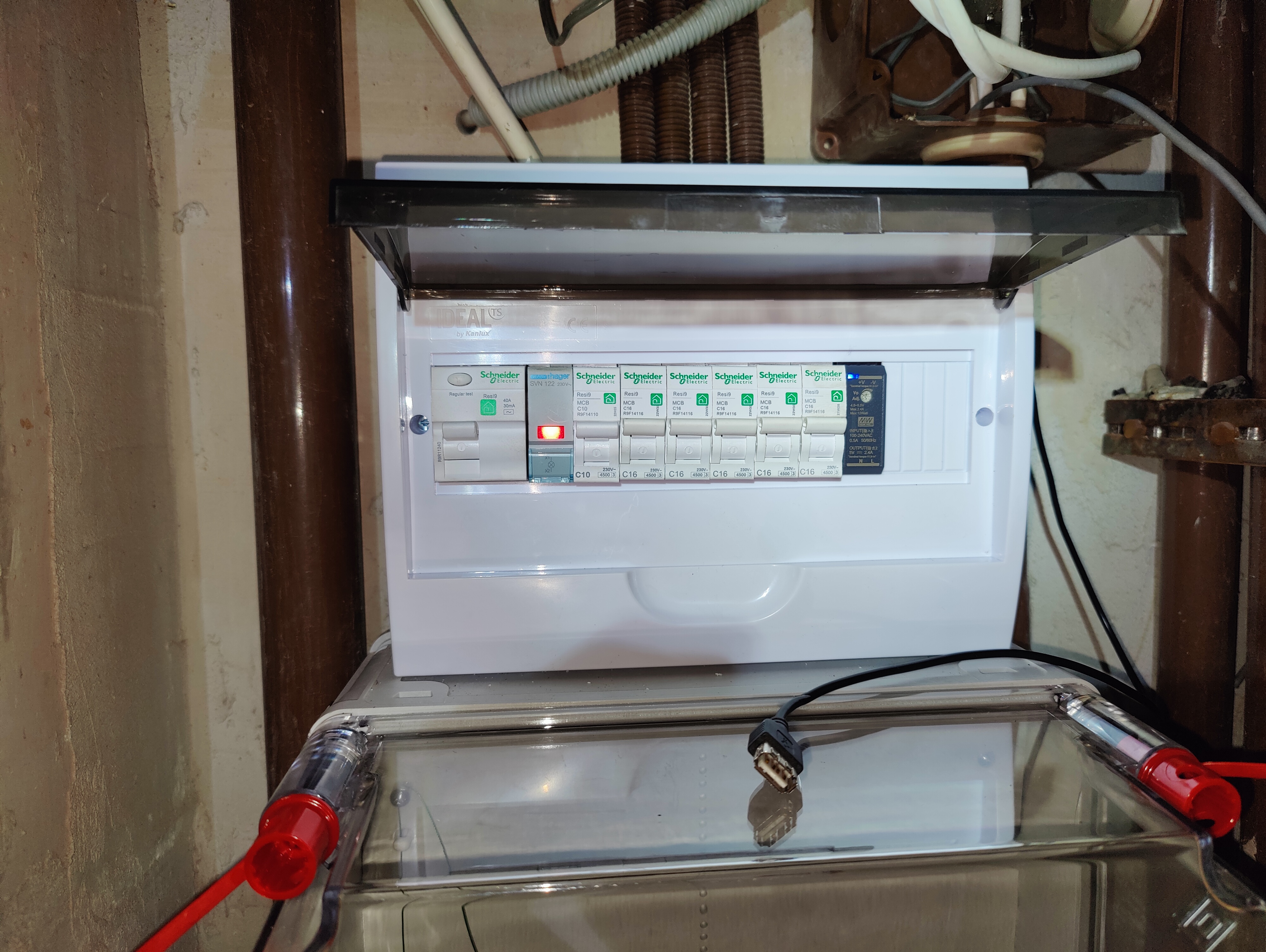
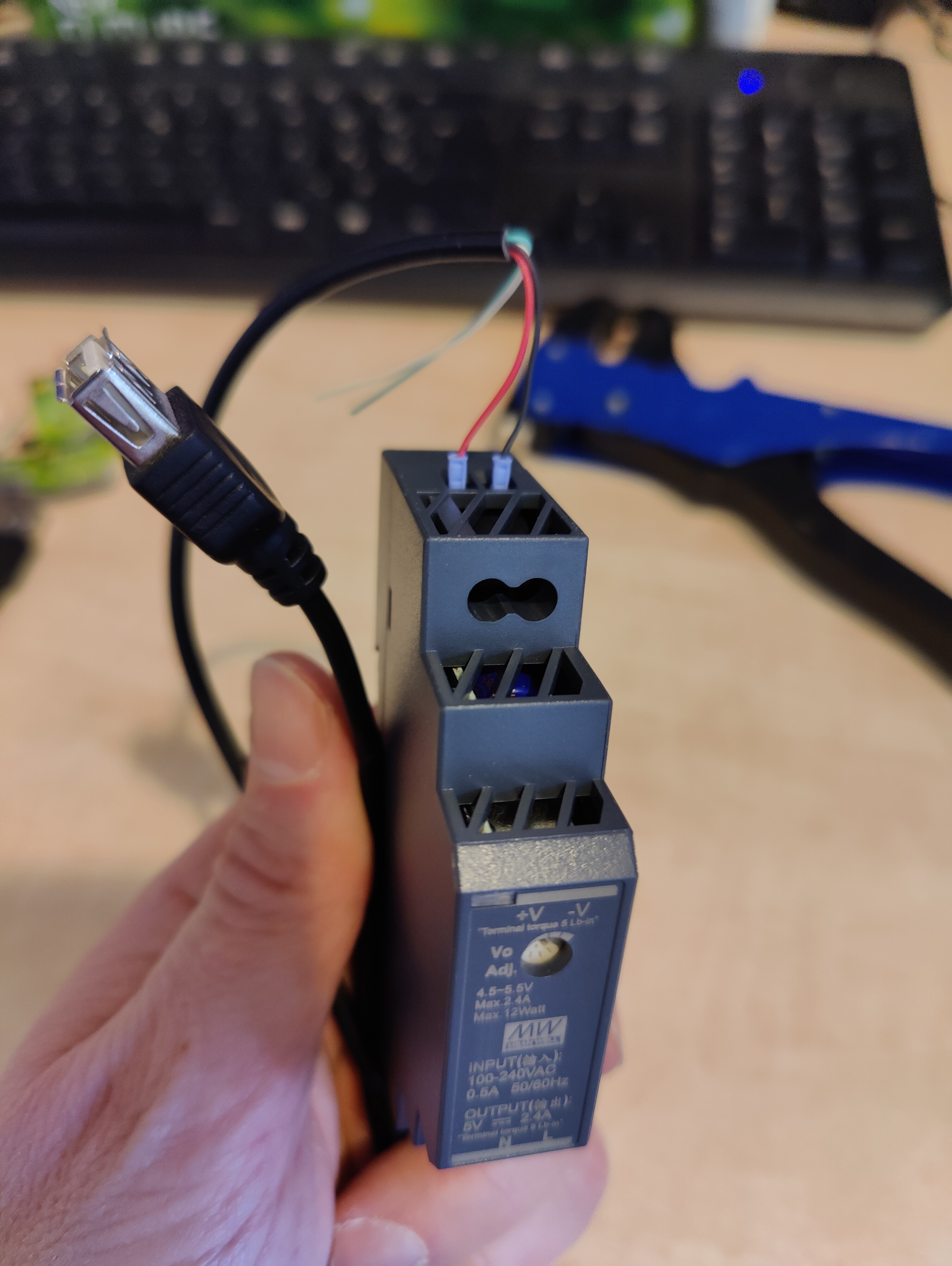
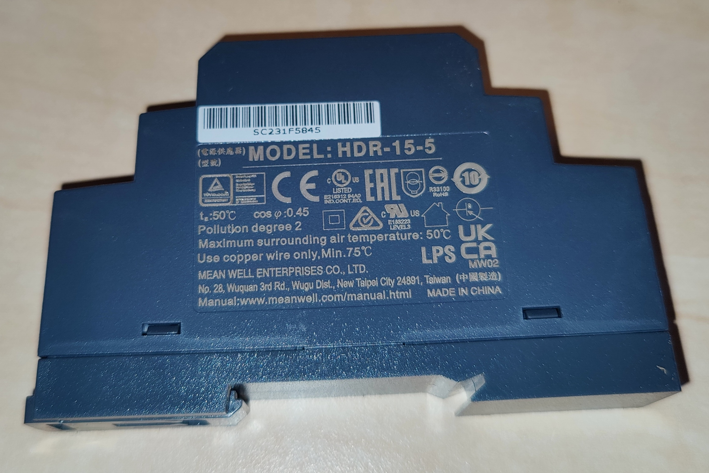
Wemos can be powered from USB as well as via the 3.3V/5V DC holes on the borad. Fortunatelly, P1 port can feed your wemos via the 5V pinout so you don’t need to worry about. However, in case of meters without P1 port you have to use the optical port where there is no power source you can use. In this case I use Meanwell HDR-15-5 DIN rail mountable DC adapter with a USB cable attached to it but a standard mobile phone charger can be used too if it fits more for you.
Regarding the software will run on the ESP chip: there are different options. You can write it by your own in C/C++ or in Python on top of Micropython or use ESPhome but for me Tasmota looks the most handy solution: it supports many different hardware like Sonoff POW I also use and it has user interfaces such as easy-to-use web interface or MQTT.
I doesn’t go into the deep details how you need to build your Tasmota and flash your ESP device with it but I drop snippets and links here to make your life a bit easier.
Here at Tasmota’s documentation page there is a copmrehensive description about the options how you can create your custom build necessary for both optical and P1 port meters. The most handy way, I think, is the Gitpod based one but it’s up to you, of course.
Important: please refer to the sections below to find out how to wire your board and what are the custom build options you need to use when you build your custom Tasmota depending on the meter communication interface!
Tasmota documented the exact way of flashing too. For people with limited domain knowledge there is a web browser based solution. I add here how I flash my Wemos D1 mini R2 board with esptool on Ubuntu 22.04.3 LTS linux from terminal:
halacs@halacs1:/tmp$ esptool --port /dev/ttyUSB0 write_flash -fs 1MB -fm dout 0x0 tasmota-p1-12.4.bin
esptool.py v2.8
Serial port /dev/ttyUSB0
Connecting....
Detecting chip type... ESP8266
Chip is ESP8266EX
Features: WiFi
Crystal is 26MHz
MAC: [REDACTED]
Enabling default SPI flash mode...
Configuring flash size...
Erasing flash...
Took 2.89s to erase flash block
Wrote 699392 bytes at 0x00000000 in 69.0 seconds (81.1 kbit/s)...

Leaving...
Hard resetting via RTS pin...
After flashing Wemos D1 mini with Tasmota, set Module type to 18 Generic via web interface. The easiest is as suggested here. Then do all the necessary configurations such as Wifi network and MQTT settings. This post won’t cover these. They are quite straithforward on the web interface and very well documented on Teasmota’s site.
Now you have a working ESP device with Tasmota so it’s time to add the power meter specific configuration and physical wiring.
Metric collector device for P1
As I mentioned above, P1 port is far the best way the communicate with power meters.
Below you can find a schematic how to wire your board and the meter’s P1 socket properly. It is simple.
I drop below the Tasmota custom build options to enable necessary features for the script parsing data continusly sent by the wemos via serial interface.
If you need more details you can continue reading here at Tasmota’s site.
Community published scripts for other meters too here. Feel free to support community and publish your script if you create a new one for a new meter. I did it alredy :)
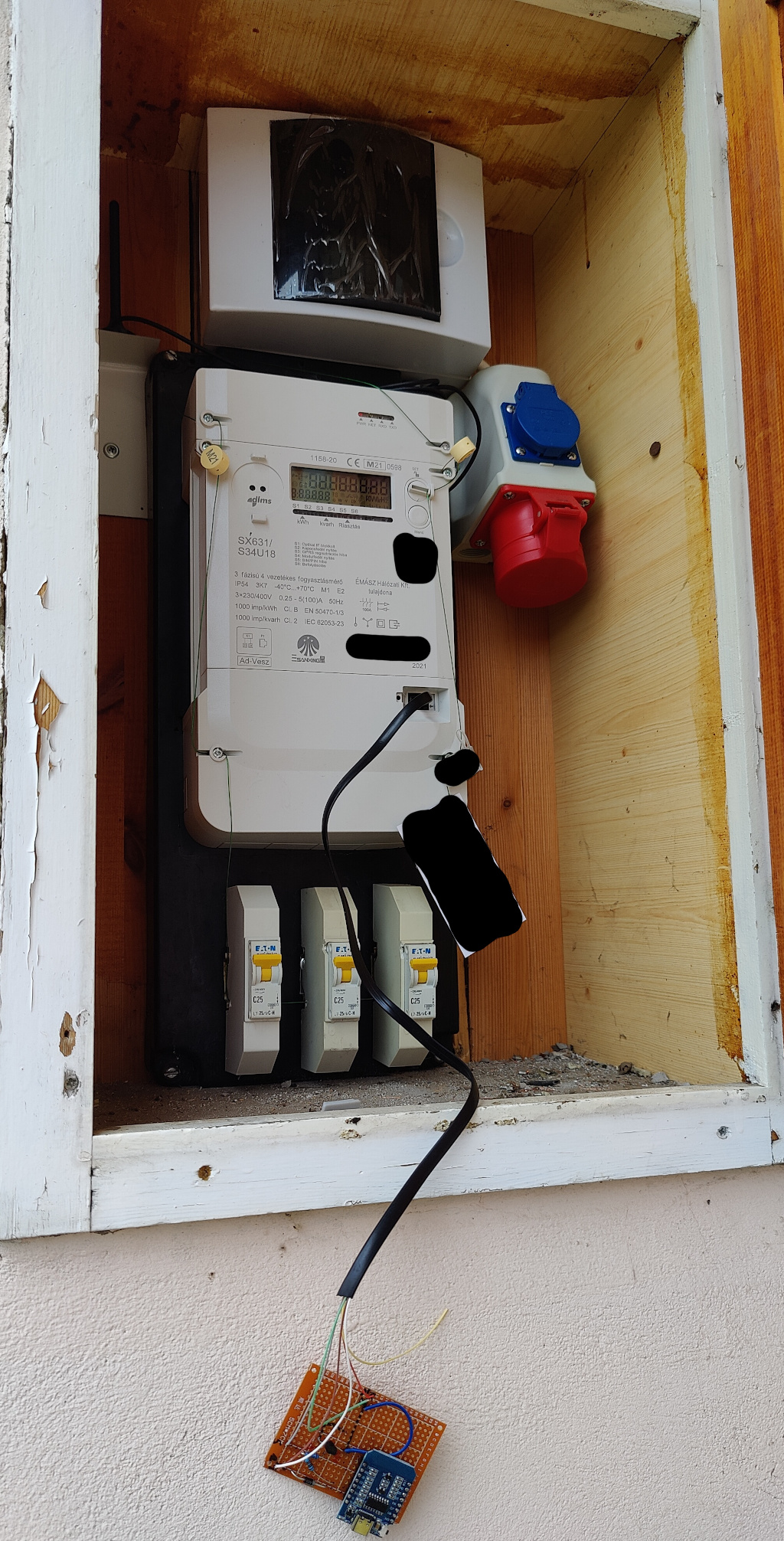
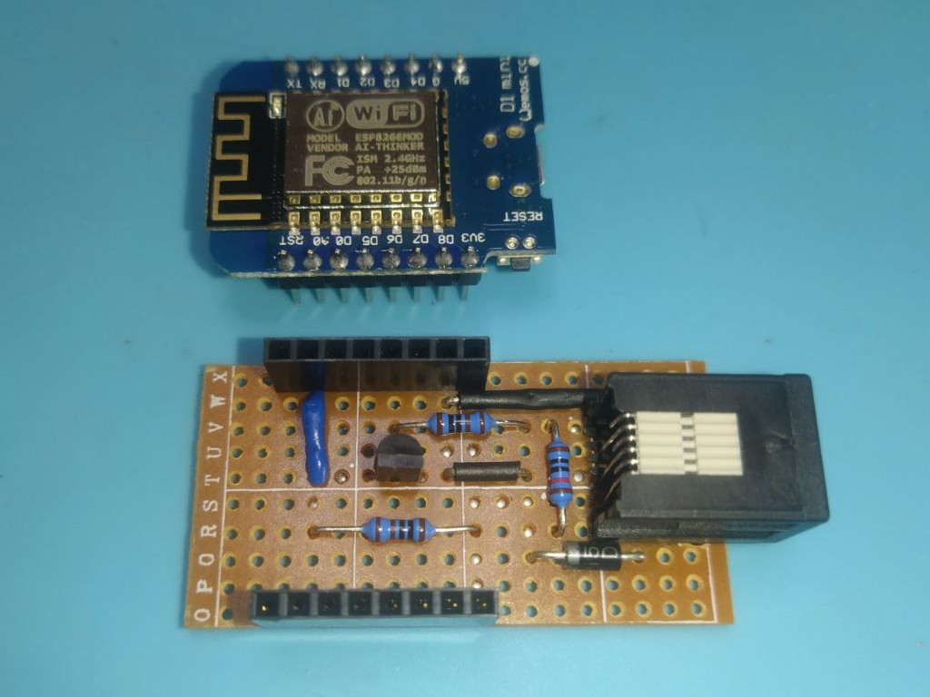
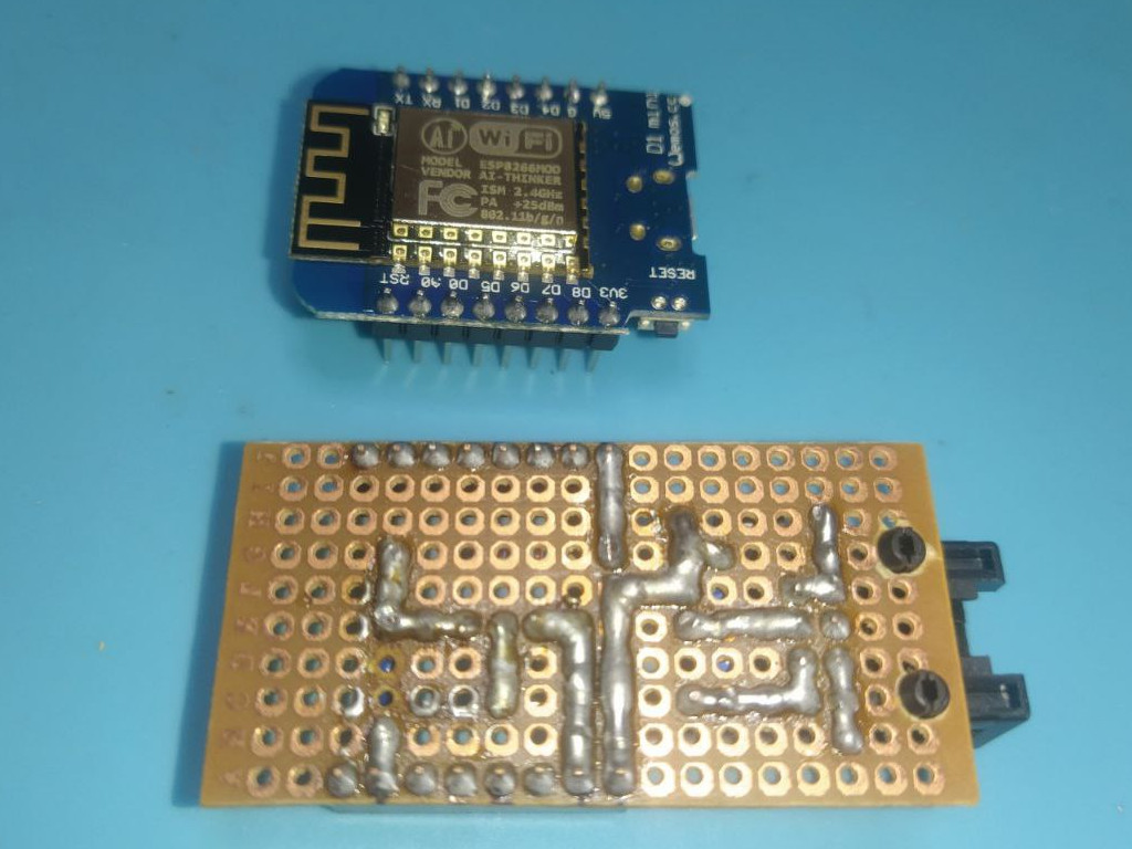
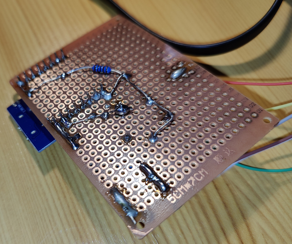
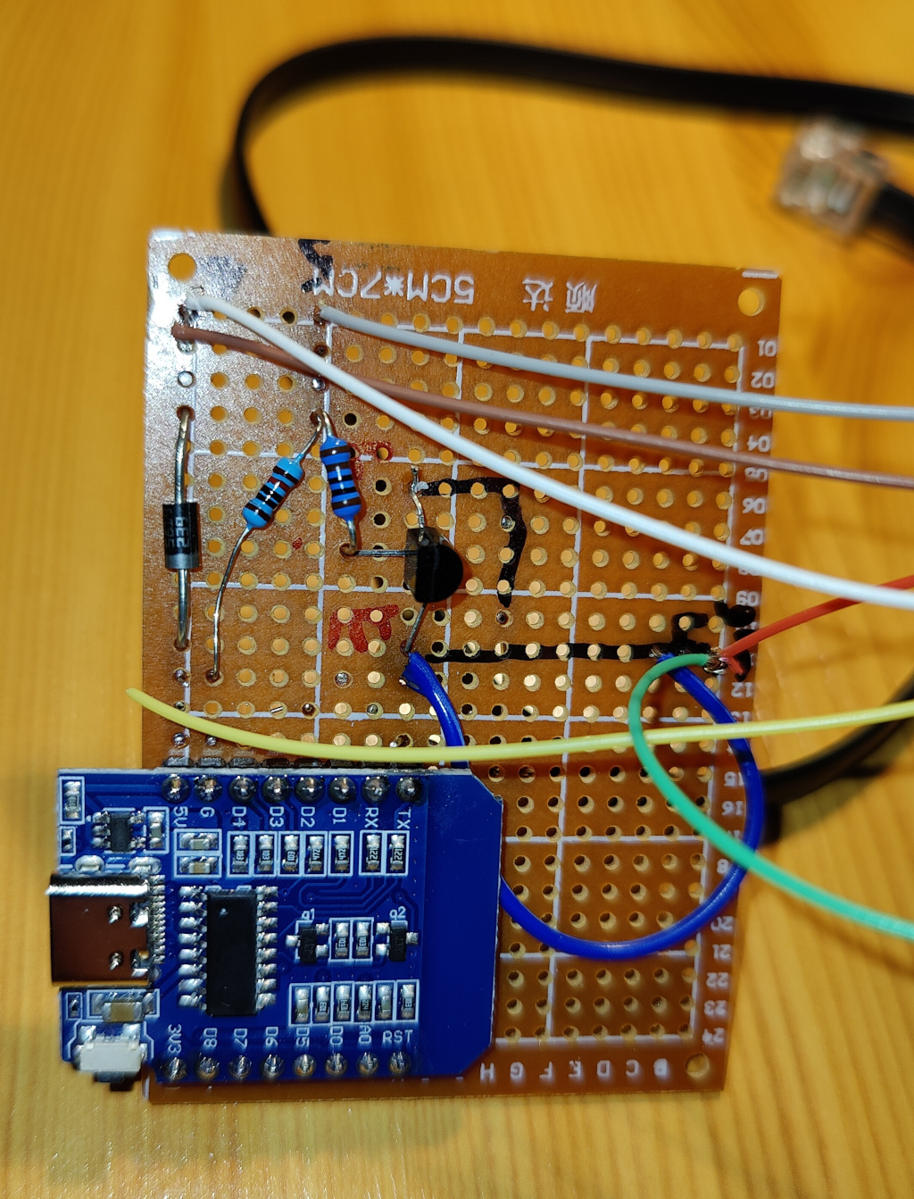
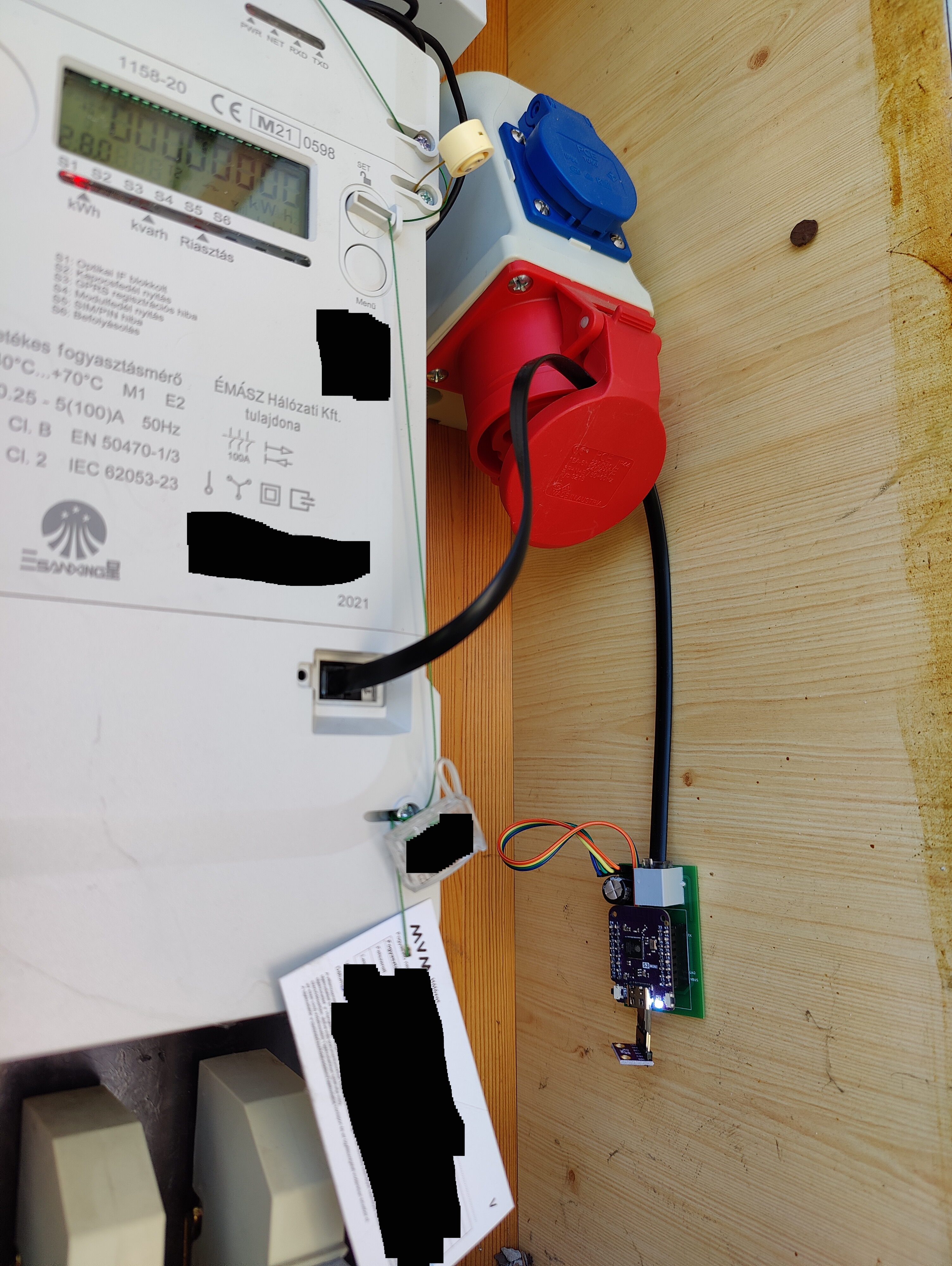
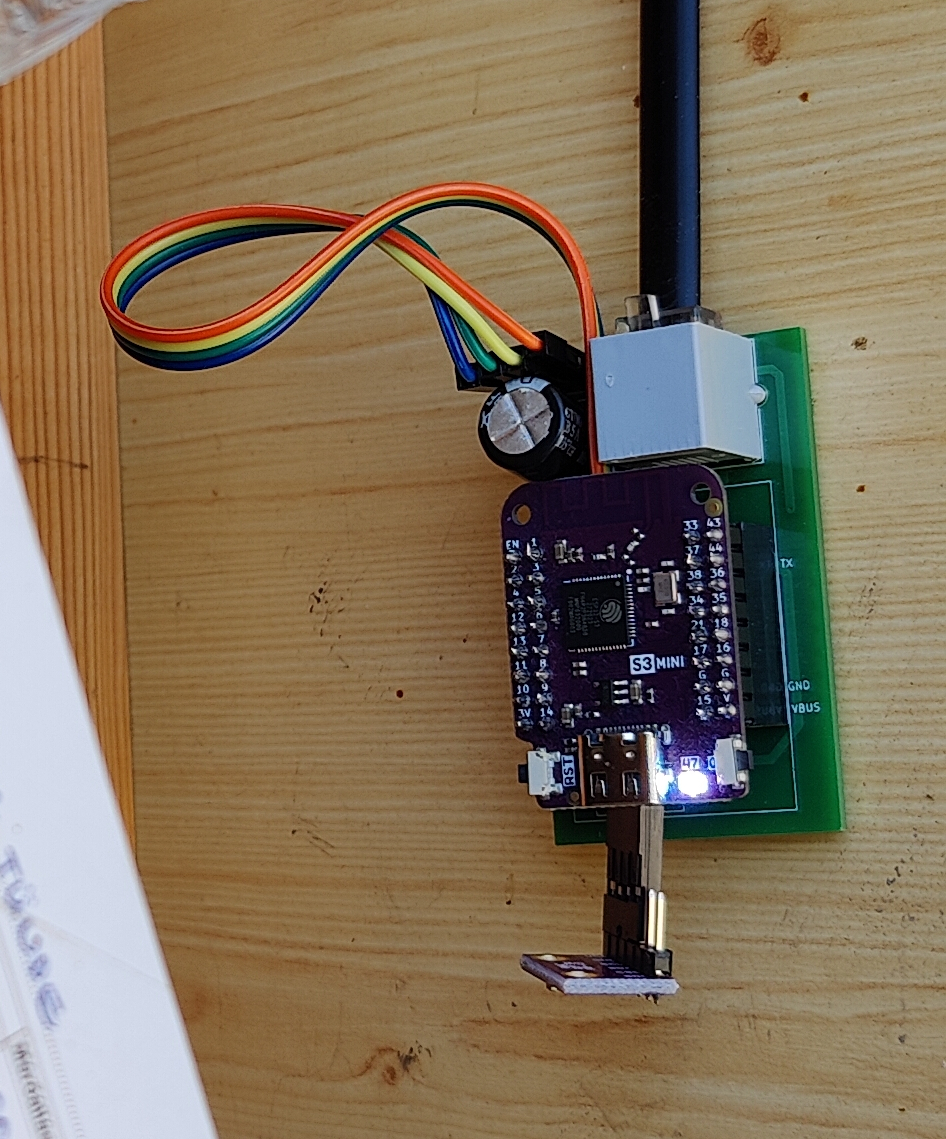
Final solution looks like here in my case. My board is a bit rude but works very well. A friend of mine made a much nicer board so I add it too to show it is also possible even at home :)
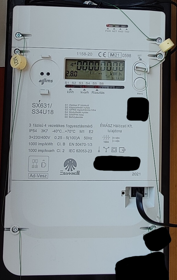
Content of Tasmota’s user_override.h file for dlms SX631/S34U18 electicity meter
#ifndef USE_SCRIPT
#define USE_SCRIPT
#endif
#ifndef USE_SML_M
#define USE_SML_M
#endif
#ifdef USE_RULES
#undef USE_RULES
#endif

#define SML_BSIZ 2048
#define MAX_METERS 1
#define TMSBSIZ 4096
#define USE_SML_SCRIPT_CMD
#define SML_REPLACE_VARS
Tasmota script for dlms SX631/S34U18 electicity meter
>D
r="1,0-0:98.1.0(@("
>B
smlj=0
->sensor53 r
>R
smlj=0
>S
if upsecs>22
then
smlj=1
endif
>M 1
+1,3,o,16,115200,EON,1
1,1-0:32.7.0(@1,L1 Voltage,V,volts_l1,1
1,1-0:31.7.0(@1,L1 Current,A,amps_l1,1
1,1-0:52.7.0(@1,L2 Voltage,V,volts_l2,1
1,1-0:51.7.0(@1,L2 Current,A,amps_l2,1
1,1-0:72.7.0(@1,L3 Voltage,V,volts_l3,1
1,1-0:71.7.0(@1,L3 Current,A,amps_l3,1
1,1-0:14.7.0(@1,Frequency,Hz,freq,2
1,0-0:96.14.0(@1,Current tariff,,tariff,0
1,=h<hr/>
1,1-0:1.7.0(@1,Current power import,kW,pwr_imp,3
1,1-0:1.8.0(@1,Energy import,kWh,enrg_imp,3
1,1-0:1.8.1(@1,Energy import T1,kWh,enrg_imp_t1,3
1,1-0:1.8.2(@1,Energy import T2,kWh,enrg_imp_t2,3
1,1-0:3.8.0(@1,Reactive nrg import,kvarh,nrg_reac_imp,3
1,=h<hr/>
1,1-0:2.7.0(@1,Current power export,kW,pwr_exp,3
1,1-0:2.8.0(@1,Energy export,kWh,enrg_exp,3
1,1-0:2.8.1(@1,Energy export T1,kWh,enrg_exp_t1,3
1,1-0:2.8.2(@1,Energy export T2,kWh,enrg_exp_t2,3
1,1-0:4.8.0(@1,Reactive nrg export,kvarh,nrg_reac_exp,3
1,=h<hr/>
1,1-0:15.8.0(@1,Energy combined,kWh,enrg_comb,3
1,1-0:13.7.0(@1,Power factor,,factor,3
1,=h<hr/>
1,1-0:5.8.0(@1,Reactive energy QI,kvarh,nrg_reac_q1,3
1,1-0:6.8.0(@1,Reactive energy QII,kvarh,nrg_reac_q2,3
1,1-0:7.8.0(@1,Reactive energy QIII,kvarh,nrg_reac_q3,3
1,1-0:8.8.0(@1,Reactive energy QIV,kvarh,nrg_reac_q4,3
1,1-0:5.7.0(@1,Reactive power QI,kvar,pwr_reac_q1,3
1,1-0:6.7.0(@1,Reactive power QII,kvar,pwr_reac_q2,3
1,1-0:7.7.0(@1,Reactive power QIII,kvar,pwr_reac_q3,3
1,1-0:8.7.0(@1,Reactive power QIV,kvar,pwr_reac_q4,3
1,=h<hr/>
1,=h<h3>Previous month stats:</h3>
%r%1:1,Energy import,kWh,mo_enrg_imp,3
%r%2:1,Energy import T1,kWh,mo_enrg_impt1,3
%r%3:1,Energy import T2,kWh,mo_enrg_impt2,3
%r%14:1,Peak power import L1,kW,mo_pw_pk_in_l1,3
%r%15:1,Peak power import L2,kW,mo_pw_pk_in_l2,3
%r%16:1,Peak power import L3,kW,mo_pw_pk_in_l3,3
%r%7:1,Reactive nrg import,kvarh,mo_nrg_reac_imp,3
%r%4:1,Energy export,kWh,mo_enrg_exp,3
%r%5:1,Energy export T1,kWh,mo_enrg_expt1,3
%r%6:1,Energy export T2,kWh,mo_enrg_expt2,3
%r%17:1,Peak power export L1,kW,mo_pw_pk_ex_l1,3
%r%18:1,Peak power export L2,kW,mo_pw_pk_ex_l2,3
%r%19:1,Peak power export L3,kW,mo_pw_pk_ex_l3,3
%r%8:1,Reactive nrg export,kvarh,mo_nrg_reac_exp,3
%r%9:1,Reactive energy QI,kvarh,mo_nrg_reac_q1,3
%r%10:1,Reactive energy QII,kvarh,mo_nrg_reac_q2,3
%r%11:1,Reactive energy QIII,kvarh,mo_nrg_reac_q3,3
%r%12:1,Reactive energy QIV,kvarh,mo_nrg_reac_q4,3
%r%13:1,Reactive energy SUM?,kvarh,mo_nrg_reac_sum,3
#
Metric collector device for optical interface
From data processing point of view, P1 and optical interaces are quite similar. Documentation of Tasmota talks about it here.
Because of same reason, I again have to refer this page of Tasmota documentation where further scripts can be found for a wide range of meters.
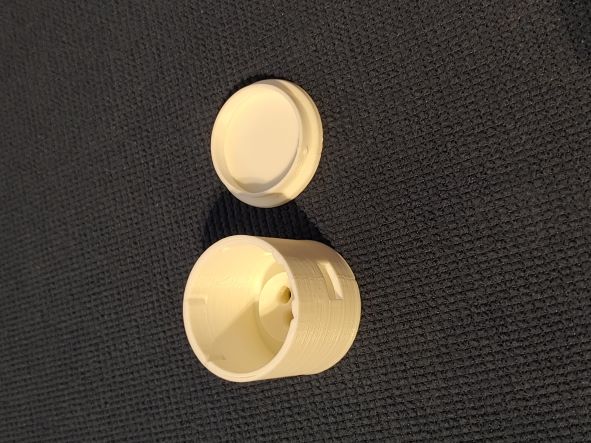
In case of optical port only meters, you might wirth to use ESP01S borad instead of Wemos D1 mini. It can be a good choice just because of its physical dimensions: there is a 3D printable model on the Internet to give it a more professional look and feel.
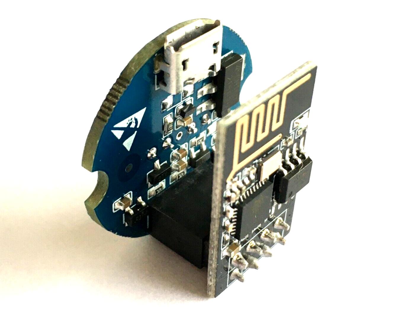
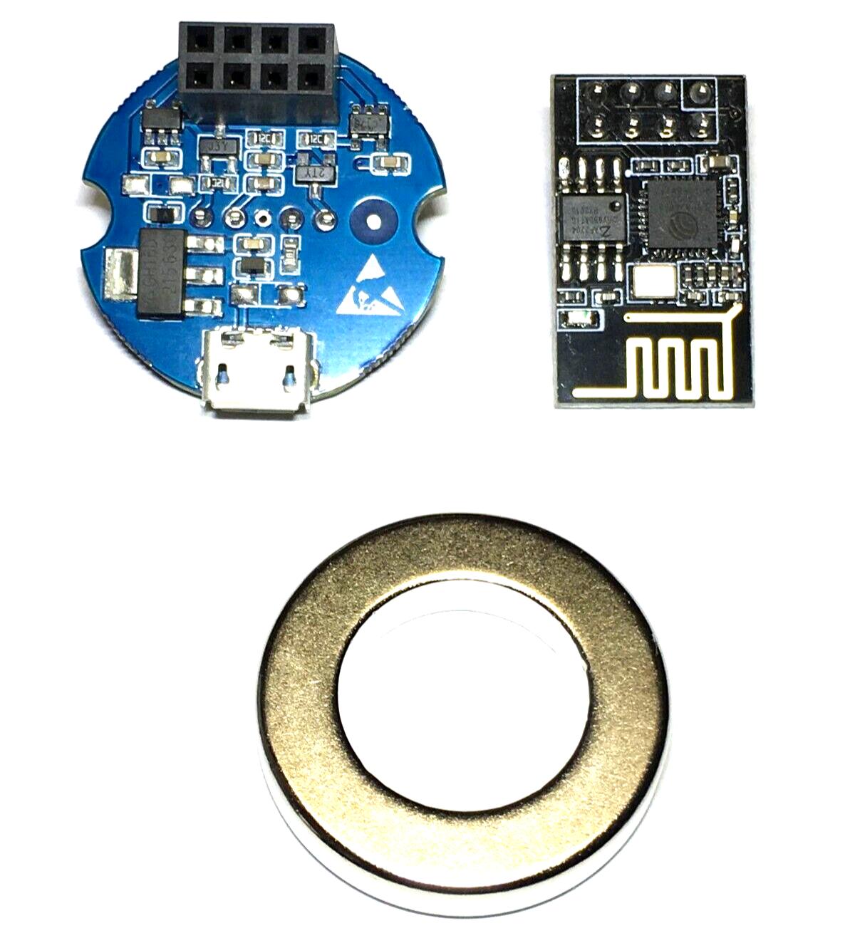
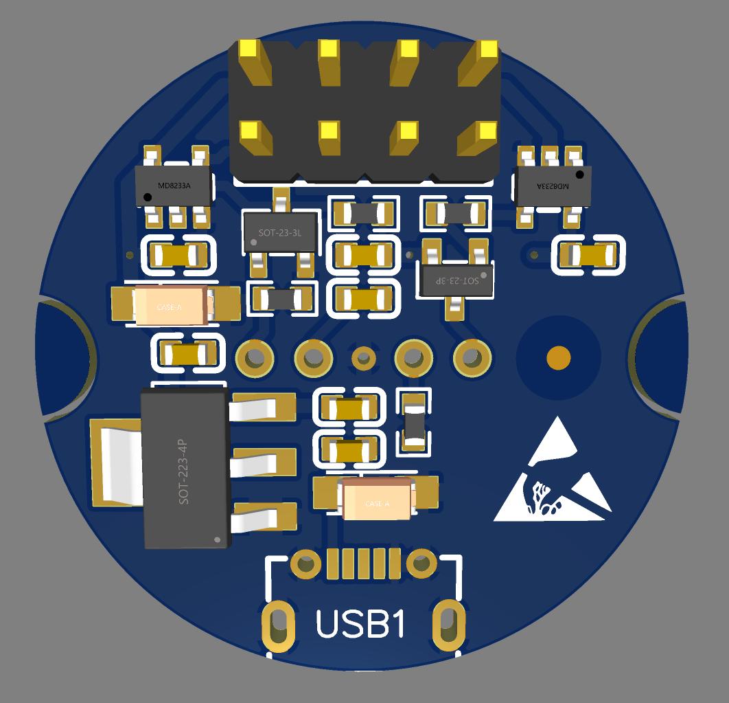
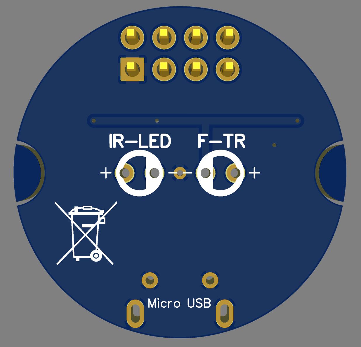
Beyond the ESP, the optical communication head is the most important part of the story. I bougth it from here via ebay. Seller (arelektronik) is very friendly with good communication so I can just suggest business with. You can buy (almost) everything you need from that shop:
- Matching ESP01S microcontroller board
- Optical interface
- Ring magnet
What you need to manage from other sources:
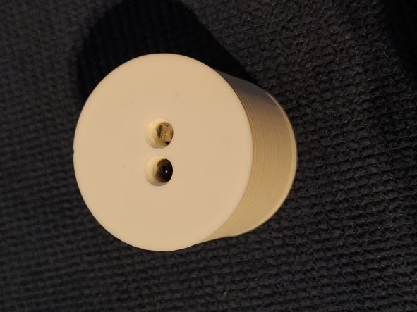
- plastic box. Can be 3D printed from this model from thingiverse.com.
- external 5V DC power source. I use Meanwell HDR-15-5 but any mobile phone charger is fine.
So far I use Wemos D1 mini for optical communication too like for P1 but I plan to switch to ESP01S instead later when I will have time to do so. To be honest, I don’t really care about how it looks like in a closed and almost never opened chassie while knowledge sharing is always more useful :)
Whenever you want to use ESP01S instead of Wemos D1 mini, you will need to have a USB flasher device as it does not have USB port you can use to flash even if you connect your ESP module to the optical head. On the USB port of the link optical head only 5VDC is wired out so look for a good ESP01 flasher device on ebay. It’s cheap but good to know about this extra requirement because of the long delivery time.
Gallery:
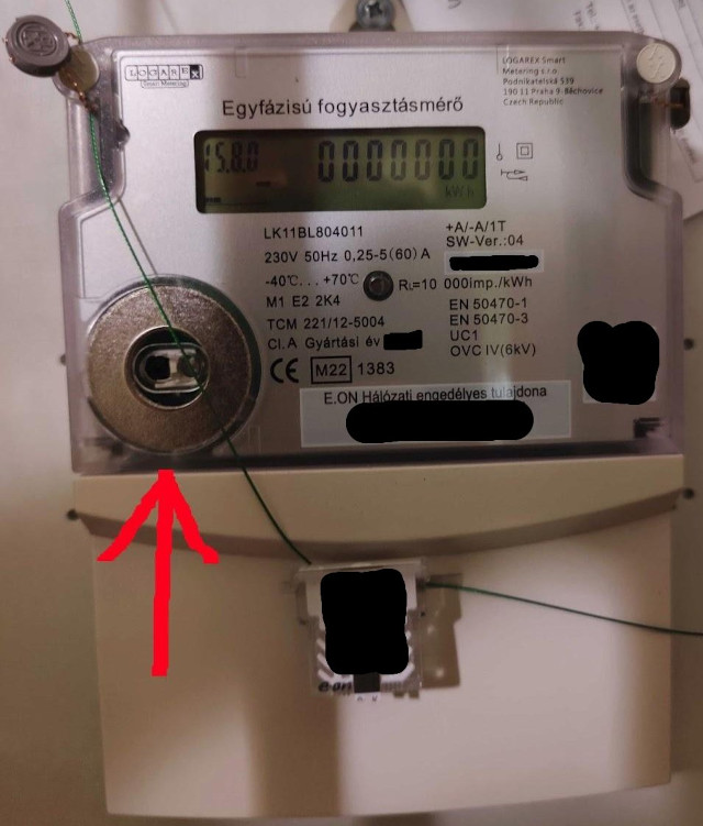
Content of Tasmota’s user_override.h file for Logarex LK11BL804011 electicity meter
#ifndef USE_SCRIPT
#define USE_SCRIPT
#endif

#ifndef USE_SML_M
#define USE_SML_M
#endif

#ifdef USE_RULES
#undef USE_RULES
#endif

#ifndef USE_SML_SCRIPT_CMD
#define USE_SML_SCRIPT_CMD
#endif
#endif
Tasmota script for Logarex LK11BL804011 electicity meter
>D
>B
=>sensor53 r
>M 1
+1,3,o,0,300,zm,1,100,2F3F210D0A,060000D0A

1,15.8.0(@1,total,kWh,total,3
1,0.0.0(@1,serial,,serial,0
1,F.F(@1,F.F,,F.F,0
1,C.8.0(@1,C.8.0,,C.8.0,0
1,0.2.0(@#),ver,,ver,3
1,0.3.0(@1,0.3.0,imp/kWh,0.3.0,0
1,.8.1(@1,.8.1,,.8.1,0
1,C.7.1(@1,C.7.1,,C.7.1,0
1,C.2.1(@1,C.2.1,,C.2.1,0
1,C.2.9(@1,C.2.9,,C.2.9,0
#
Forward, store and visualize
You already know that I use Tasmota on top of Wemos D1 mini hardware to read metrics from the utility meter but how I forward the collected data? Well, Tamosta can forward all of them to my Mosquitto MQTT broker. MQTT stands for Message Queuing Telemetry Transport and it is a service on my server.
According to Wikipedia, MQTT broker is “a lightweight, publish-subscribe, machine to machine network protocol for message queue/message queuing service. It is designed for connections with remote locations that have devices with resource constraints or limited network bandwidth, such as in the Internet of Things (IoT).”
On the other side of the MQTT server, I have an mqttwarn. It is a highly configurable message router written in Python. Lots of plugins make it so powerful. Most important plugin now is the influxdb writer plugin which stores received values in influxdb database.
Wikipedia defines influxdb database as “an open-source time series database developed by the company InfluxData. It is used for storage and retrieval of time series data in fields such as operations monitoring, application metrics, Internet of Things sensor data, and real-time analytics.”
Finally, I have to visualise somehow the data already stored in our time series database described above. I selected Grafana for this purpose. “Grafana is a multi-platform open source analytics and interactive visualization web application. It provides charts, graphs, and alerts for the web when connected to supported data sources.” – Wikipedia
For more information, please refer to the link above, however, I put a snippet here from my mqttwarn configuration. There is a section for P1 port meters and another for meters with only optical ports. Please note, that format lines are more or less specific to the exact meter types are described in this post.
[config:influxdb]
host      = '127.0.0.1'
port      = 8086
username  = '[REDACTED]'
password  = '[REDACTED]'
database  = 'iot'
precision = 's'    # { ns, u, ms, s, m, h }
targets = {
    'electricmeter'                : [ 'electricmeter' ],
    }

# For meter with P1 port
[home1/tele/myelectricmeter/SENSOR]
targets = influxdb:electricmeter
format = device=home1 volts_l1={EON[volts_l1]},amps_l1={EON[amps_l1]},volts_l2={EON[volts_l2]},amps_l2={EON[amps_l2]},volts_l3={EON[volts_l3]},amps_l3={EON[amps_l3]},freq={EON[freq]},tariff={EON[tariff]},pwr_imp={EON[pwr_imp]},enrg_imp={EON[enrg_imp]},enrg_imp_t1={EON[enrg_imp_t1]},enrg_imp_t2={EON[enrg_imp_t2]},nrg_reac_imp={EON[nrg_reac_imp]},pwr_exp={EON[pwr_exp]},enrg_exp={EON[enrg_exp]},enrg_exp_t1={EON[enrg_exp_t1]},enrg_exp_t2={EON[enrg_exp_t2]},nrg_reac_exp={EON[nrg_reac_exp]},enrg_comb={EON[enrg_comb]},factor={EON[factor]},nrg_reac_q1={EON[nrg_reac_q1]},nrg_reac_q2={EON[nrg_reac_q2]},nrg_reac_q3={EON[nrg_reac_q3]},nrg_reac_q4={EON[nrg_reac_q4]},pwr_reac_q1={EON[pwr_reac_q1]},pwr_reac_q2={EON[pwr_reac_q2]},pwr_reac_q3={EON[pwr_reac_q3]},pwr_reac_q4={EON[pwr_reac_q4]},mo_enrg_imp={EON[mo_enrg_imp]},mo_enrg_impt1={EON[mo_enrg_impt1]},mo_enrg_impt2={EON[mo_enrg_impt2]},mo_pw_pk_in_l1={EON[mo_pw_pk_in_l1]},mo_pw_pk_in_l2={EON[mo_pw_pk_in_l2]},mo_pw_pk_in_l3={EON[mo_pw_pk_in_l3]},mo_nrg_reac_imp={EON[mo_nrg_reac_imp]},mo_enrg_exp={EON[mo_enrg_exp]},mo_enrg_expt1={EON[mo_enrg_expt1]},mo_enrg_expt2={EON[mo_enrg_expt2]},mo_pw_pk_ex_l1={EON[mo_pw_pk_ex_l1]},mo_pw_pk_ex_l2={EON[mo_pw_pk_ex_l2]},mo_pw_pk_ex_l3={EON[mo_pw_pk_ex_l3]},mo_nrg_reac_exp={EON[mo_nrg_reac_exp]},mo_nrg_reac_q1={EON[mo_nrg_reac_q1]},mo_nrg_reac_q2={EON[mo_nrg_reac_q2]},mo_nrg_reac_q3={EON[mo_nrg_reac_q3]},mo_nrg_reac_q4={EON[mo_nrg_reac_q4]},mo_nrg_reac_sum={EON[mo_nrg_reac_sum]}

# For meter with optical port
[home2/tele/myelectricmeter/SENSOR]
targets = influxdb:electricmeter
format = device=home2 total={zm[total]},serial={zm[serial]},F.F={zm[F.F]},0.3.0={zm[0.3.0]},.8.1={zm[.8.1]},C.7.1={zm[C.7.1]},C.2.1={zm[C.2.1]},C.2.9={zm[C.2.9]},version="{zm[ver]}",C.8.0={zm[C.8.0]}
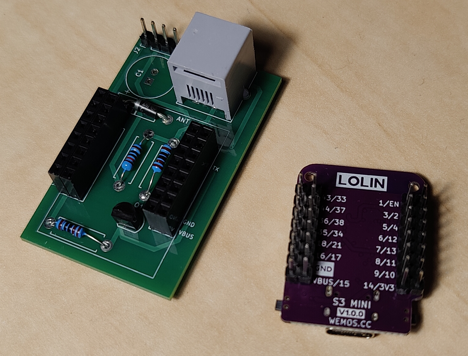
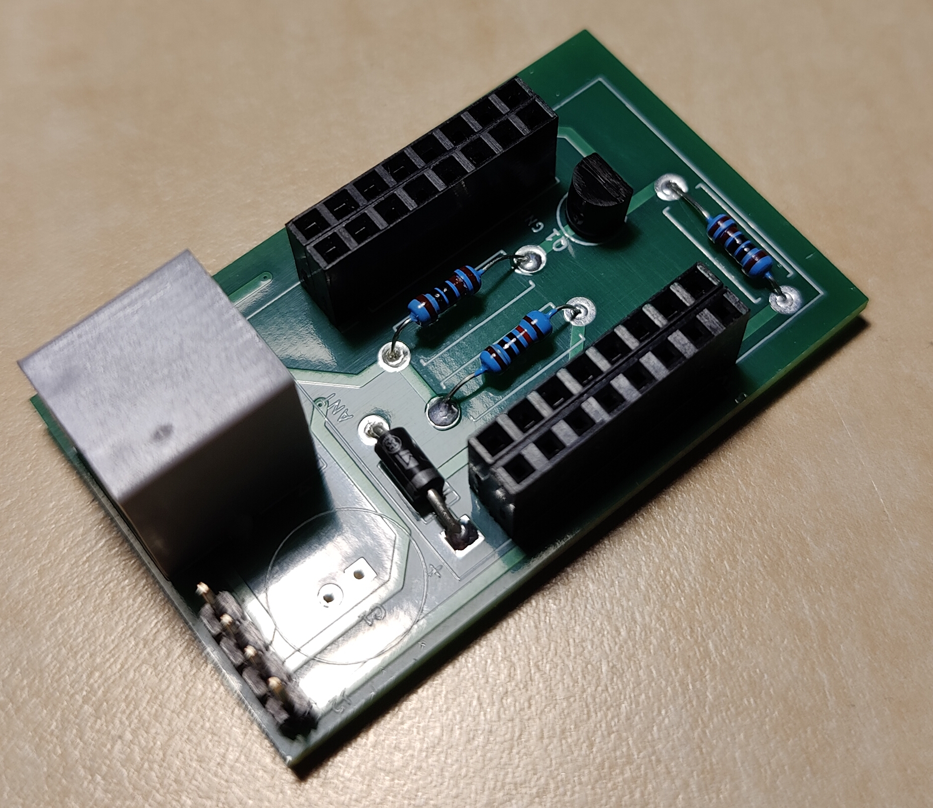
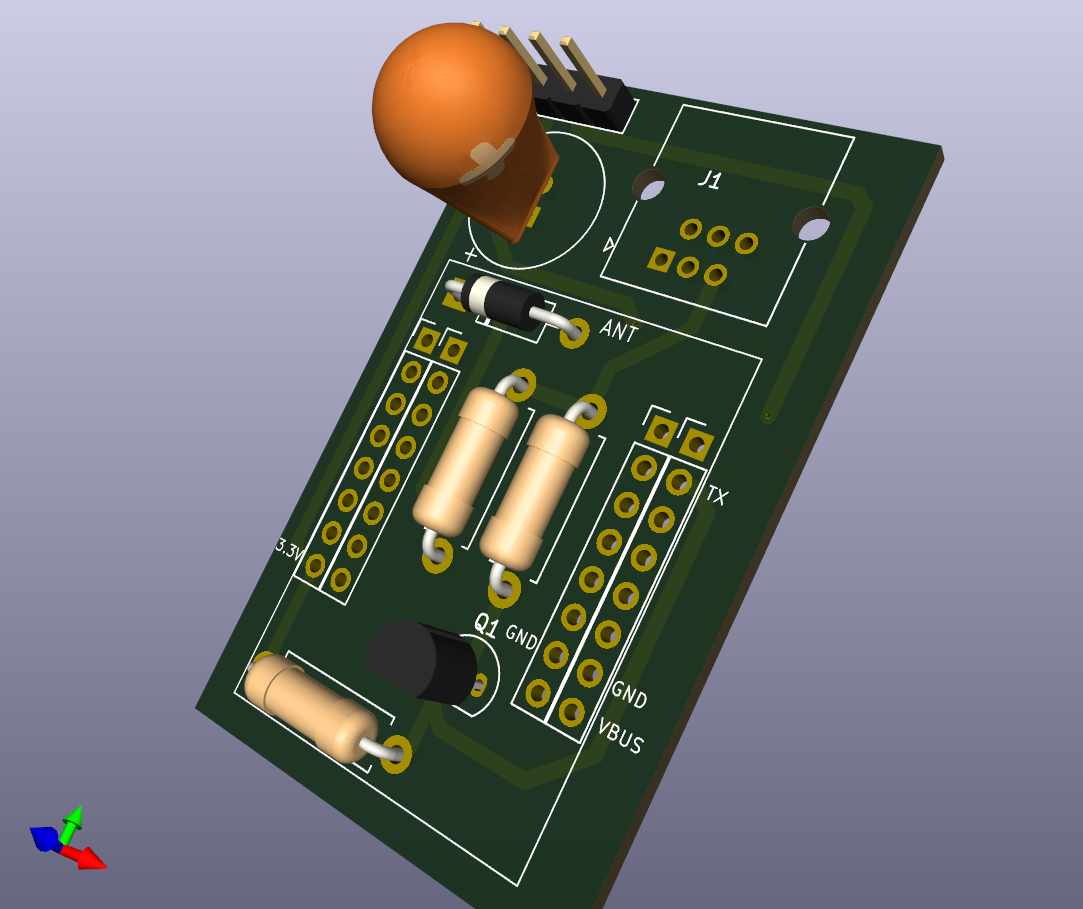
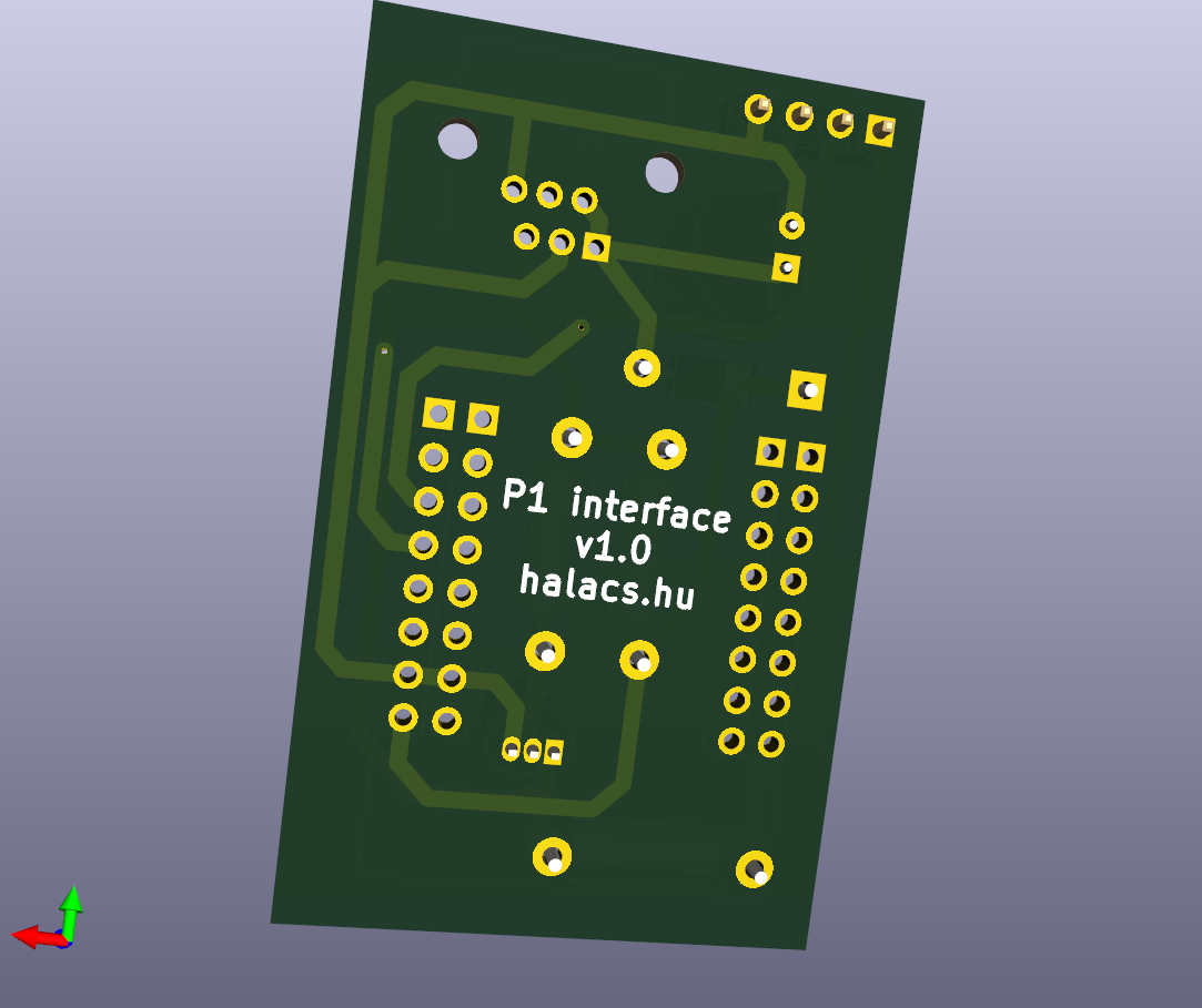
Update
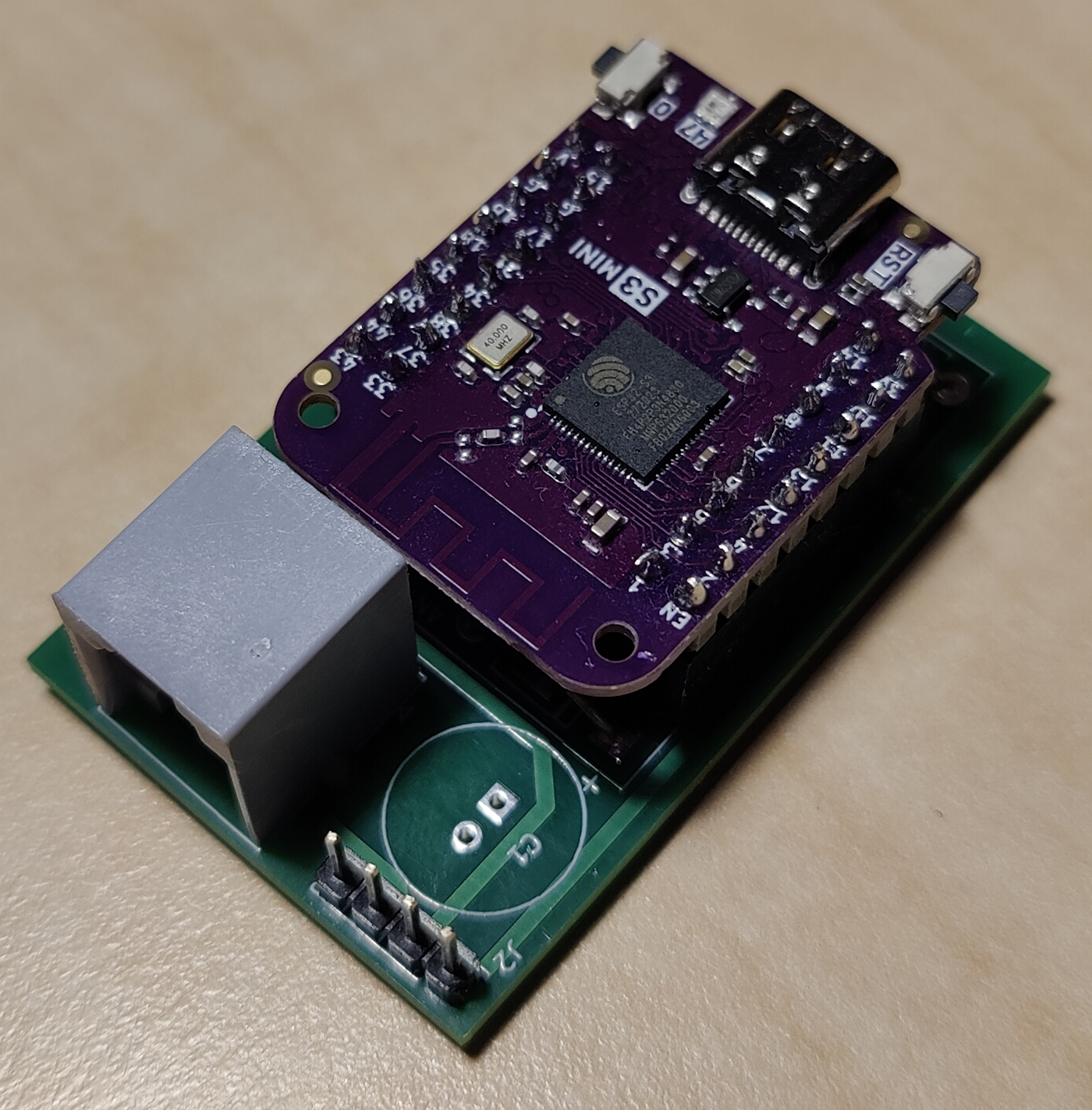
After a few months working with my “very nice” hand made PCB, I wanted to have a more professional one based on a Wemos S3 Mini board. In contrast with Wemos D1 Mini, this board gives you more memory to do such a things as TLS protected MQTT connection. And, of course, looks much better.
I still don’t have a proper plastic box for it but anyway. By the way, can you draw a 3D printable one? :)
There is an I2C connector (J2) in the top left corner for external devices such as temperature sensor. Currently, I measure the temperature and air pressure with a BMP280 sensor.
C1 capacitor is optional but might be useful: it is there because of the 250 mA power limitation of the DSMR standard.
You can find the whole project on GitHub.
References
Related standards
- Optical reading: DLMS/COSEM
- IEC 62056-21 Electricity metering - Data exchange for meter reading, tariff and load control - Part 21: Direct local data exchange
- IEC 62056-21 Communications Protocol - Reference guide
- P1 port: P1 Companion Standard - Dutch Smart Meter Requirements (DSMR) 5.0.2
- OBIS codes: IEC 62056-61
- Terminal: DIN 43857
- S0 pulse output: DIN 43864
Related regulations and user manuals
- Hungarian Power Distributors’ regulations and appendixes (“Elosztói Szabályzat” és “Az elosztó hálózathoz való hozzáférés együttműködési szabályai” melléklete) - Hungarian language
- Hungarian Power Distributors General terms and conditions (“ÉMÁSZ Üzletszabályzat”) - Hungarian language
- P1 port user manual from EON utility provider (“EON hálózat: P1 port felhasználói tájékoztató”) - Hungarian language
- User manual of Logarex LK11BL804011 power meter (published by EON in Hungarian language)
- 2007. évi LXXXVI. törvény a villamos energiáról (vet)
- 273/2007. (X. 19.) Korm. rendelet a villamos energiáról szóló 2007. évi LXXXVI. törvény egyes rendelkezéseinek végrehajtásáról (vhr)
Third party software components
- Tasmota Open source firmware for ESP devices
- P1 port meter support of Tasmota
- Smart Meter Interface of Tamosta